Principle of Plane Table Survey
The law of plane tabling is parallelism, meaning the rays drawn from stations to items on the paper are parallel to the lines in the stations to the objects on the ground.
The relative positions of these objects on the ground are represented with their own plotted positions about the paper and lie on the respective rays.
The table is always placed at each of the successive stations parallel into the position it occupied in the starting station. Plane tabling is a graphical way of surveying.
The fieldwork and plotting are done simultaneously, and this survey doesn’t involve using a field book(measurement book). Plane table survey is mainly acceptable for filling insider details when traversing is done with the theodolite.
Sometimes traversing with a plane table might also be done. However, this survey is recommended for the work where great accuracy isn’t required. As the fixing and fitting arrangement of this instrument is not perfect, most accurate work cannot be expected.
The simplest and the most commonly used plane table is as shown in as per below figure. It is known as a traverse table. It consists of a board made up of a well-seasoned wood mounted a light tripod with suitable mounting and clamping devices.
The board can rotate about a vertical axis and can be clamped in any position. The table is to be leveled by adjusting the tripod.
Johnson’s plane table and coast survey plane tables are the improved versions. In Johnson’s plane table ball and socket joint and a vertical spindle are provided while in coast survey plane table three-foot screws are provided for quick and accurate leveling.
Plane Table Survey Instruments:
- Alidade or Sight Rule
- Plumbing Fork with Plumb Bob
- Spirit Level
- Trough Compass
- Drawing Sheet and Miscellaneous Accessories for Drawing.
Alidade or Aight Rule
An alidade is a straight-edge ruler using some form of sighting device.One advantage of this ruler is a beveled edge that’s is also known as the fiducial edge.
This advantage is graduated and used for drawing no line of sights. Based on the type of line of sight Provided, there are two types of alidade:
- Plain Alidade
- Telescopic Alidade
Plain Alidade :
In the case of the plain alidade, a sight vane at each end of the ruler is provided, as shown in as per below figure (Ref. as per above figure also).
Among that sight, vanes are provided with a narrow slit, and it serves as eye vane. Another sight vane known as thing vane is wider and it carries horsehair or a thin wire in its center. The two vanes are provided with hinges in their base so they may be folded on the ruler if not in use.
Telescopic Alidade:
A telescopic alidade is made up of a telescope mounted on a column that’s fixed into the ruler. The size of this ruler is 380 mm long and 65 mm wide.
The line of sight by means of a telescope is kept parallel to the fiducial edge of this ruler. The telescope is supplied with a level tube along with also a vertical graduation arc. When inclined sights have taken a vertical angle of sight could be measured.
The telescope alidade is usually fitted using a stadia diaphragm and therefore may be used as a tachometer to come across horizontal distances and elevations. By providing telescope that the accuracy and the range of sight are increased.
Plumb Bob and Plumbing Fork
Plumbing fork is a U-shaped metal frame with an upper horizontal arm and a lower inclined arm as shown in as per below figure. The upper arm is provided with a pointer, whereas the lower arm is provided with a hook.
When the plumbing fork is kept on a plane table along with a plumb bob is suspended by the hook, then the plumb line moves through the end of the pointer in the upper arm.
At the start of the plane table survey, plumb bob helps in moving a ground station to the drawing sheet,& later on, it assists in transferring station positions on drawing sheets into the ground.
Spirit Level
A spirit level with a flat base is utilized for leveling plane table. To ensure proper leveling, spirit level needs to be used in two positions at right angles to one other, and leveling of the plane table ought to be ensured.
Trough Compass
Trough Compass A trough compass is made up of an 80 to 150 mm long and 30 mm wide box carrying out a freely suspended magnetic needle in its center. At the top of the box is provided with a glass cover.
In the ends of the needle, graduations are marked out of zero to five degrees on each side of the center. When the needle ends to coincide with zero-zero, the line of needle ends is parallel to the long edge of the box.
Hence, a marking on either side of a long edge indicates the north direction of the survey. Thus, the trough compass is useful for marking the north line on the drawing sheet.
Drawing Sheet and Accessories for Drawing
The drawing paper of superior quality ought to be used in a plane table survey. It ought to be well seasoned before use by exposing it alternatively to warm and moist atmosphere.
By seasoning, shrinkage of sheets in the future is reduced considerably. The sheet ought to be in a position to withstand rubbing against alidade.
The drawing sheet shouldn’t be folded. Many times two sheets attached using their grains at right angles to one another and using a sheet of muslin between them are utilized.
For works of importance, fiberglass sheets or paper backed with thin aluminum sheets are utilized. Clips, clamps and adhesive tapes /Chain might be used for fixing drawing sheet into the table. Sharp hard pencil (4 H), good quality eraser, pencil cutter and sandpaper to keep pencil point sharp are other accessories need for drawing work.
A waterproof cover such as plastic sheet ought to be carried from the surveyor, to protect drawing sheet out of the rain, if required.
Equipment Setting for Plane Table Survey:
Once fixing the table into the stand and drawing sheet into the following operations are to be carried out :
- Centering
- Leveling
- Orientation
1. Centering
Here is the process of adjusting the position of a point on the plane table exactly over its position on the ground station. This can be achieved using plumbing fork and moving legs of a tripod.
2. Levelling
Spirit level is used to check the level of the table. The level ought to be ensured in two positions of spirit level that are at right angles to one another. The legs of the tripod are moved radially or along the circumference to correct the level of the table.
3. Orientation
Orientation is the process of placing a plane table in a station such that all the lines plotted are parallel to corresponding lines on the ground.
This is a very important process in plane tabling. Accuracy of plane table survey mainly depends on how correctly at each station perfect orientation is achieved. It may be achieved by anyone of the following methods:
Using trough compass
By back sighting
By solving two-point or three-point problems.
The first two methods, which are commonly used, are explained below, and the third method is explained later in this blog.
Orientation Using Trough Compass:
After the survey work starts from the first station, the table is oriented inappropriate direction, and the north direction is marked near the right-hand top corner utilizing trough compass.
This orientation is to be kept at all subsequent stations. To acquire exactly the same orientation, trough compass is placed along the north direction marked, and the table is rotated until the compass needle is along with zero-zero readings.
Then it’s clamped. Therefore, the necessary orientation of this table is obtained. This procedure of orientation is considered rough since the local attraction to compass can impact proper orientation.
This way is used as a preliminary orientation, and finer orientation is obtained from other methods. Orientation by Back Sighting:
Orientation by Back Sighting:
It’s a commonly employed way. Before shifting the table, point in Meurment book from station A to station B, line ab is attracted from a plotted position of station A (i.e., a) towards following station B. Distance AB is Plotted and measured position b of station B is located.
Subsequently, plane table is shifted to station B and centered such that point ‘it is exactly over station B keeping the alidade along with ba station A is sighted and clamped.
This offers the required orientation. Checks could be applied by sighting already plotted objects from point `b.’
Plane Table Surveying Methods
These four methods are available for carrying out a plane table survey as per below Plane Table Surveying Methods:
- Radiation
- Intersection
- Traversing, and
- Resection
The first two methods are usually employed for locating the details whereas Another two methods are used for testing and locating the positions of plane table stations onto the drawing sheet.
1. Radiation
To fill details of objects near station ‘0′, a plane table is set on station ‘0’ the plotted position ‘0’ approximately over the ground station.
Then using alidade pivoted at ‘0’, the rays are drawn in the direction OA, OB. OC … with soft pencil [As per below Figure] Then the distances OA, OB, OC is scaled and measured down to get the plotted positions a, b, c … of field positions A, B,…Thus, these items are plotted by first drawing radial lines.
This method is acceptable for small areas, and it is convenient if the distances are small.
This method has a wider scope if the telescopic alidade is used, where distances are measured tacheometrically.
2. Intersection
Within this method, two stations are so chosen that all of the other stations to be plotted are observable from these. The line joining both of These stations is called the baseline. The length of the line is measured very accurately. Also, rays are drawn from these stations to the stations to be plotted.
The intersection of the line from the two stations provides the position of the station to be plotted onto the drawing sheet. From time to time, this way is also termed as graphical triangulation.
3. Procedure
Let A and B be the two accessible stations (as per below figure), such that A and B can be suitably plotted. C is the station to be plotted by intersection.
Place the plane table at A. Set it up. Plot the NS direction. Transfer ground station A as an onto the drawing sheet. With the alidade centered at a. sight station B.
Draw a ray aB and cut ab to a suitable scale. With the alidade at a sight, C also and draw a ray aC. Shift the table to B and set it up. Place the alidade at b and sight C. Draw a ray bC. The intersection of the two-line gives the position of station C as c on the plane table.
4. Suitability
This method is very commonly used for plotting details. It is preferred when the distance between the stations is too large, or the station’s arc inaccessible, or the ground is undulating. The most suitable example is of broken boundaries which can be very conveniently plotted by this method.
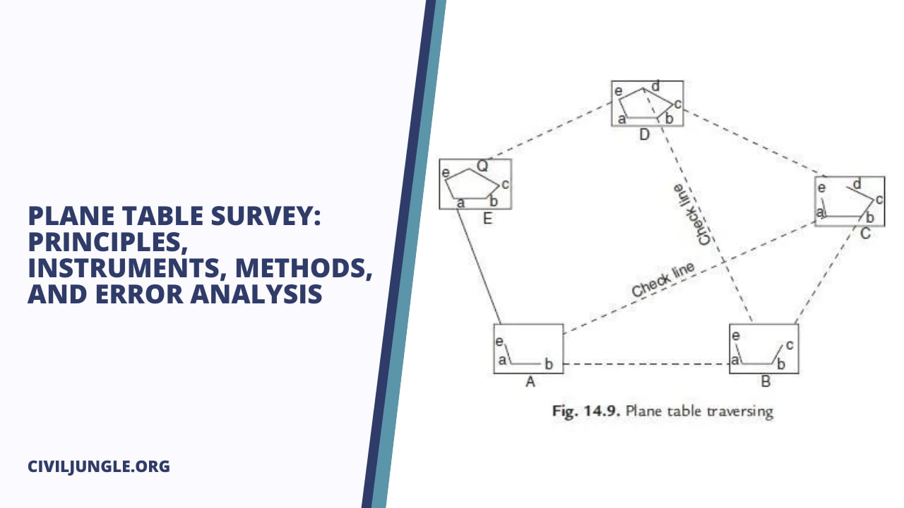
5. Traversing
This method is like a compass or a theodolite traversingy. The table is set in each of the stations in succession. A foresight is taken to another station, and the distance is cut into a suitably chosen scale.
Procedure
Set up the plane table at the initial station A (as per below figure). Transfer ground station A as an on the drawing sheet.
Draw a ray aB along the fudicial edge with the alidade pivoted against a. Cut the distance ab to the selected scale. Shift and set up the table at B. Orient the plane table.
Place the alidade at b and sight station C. Draw a ray bC along the alidade and cut the distance be to the selected scale. The procedure is carried out till all the stations are traversed.
Suitability
It’s most suited if a narrow strip of this terrain is will surveyed, e.g., a survey of streets, railways, etc. This method may be used for traversing the open in addition to close traverses.
Resection
This is an orientation technique that fixes the position of the plane table station in a plan. When a number of points already fixed by plane table or otherwise are available in plan, it is often convenient to set up the plane table at some arbitrary station and pick up detail from there.
This adds to the flexibility of a plane table survey. Conspicuous points such as temple-tops, church spires, and hilltops already fixed by any method are not convenient points on which a plane table can be set, and from which low-lying detail can be fixed.
If such points are visible from the area of the detail, the plane table can be set up to pick out the detail from an arbitrary location near it.
The position of the plane table in plan is now fixed by the resection procedure. A point determined by resection is called a plane table fix.
Error In-Plane Table Surveying
The possible error in plane table survey may be ground into
- Instrumental Errors.
- Personal Errors.
Instrumental Errors
- This type of errors are listed below.
- The surface of plane table not absolutely plane.
- Fiducial edge of alidade not straight.
- Sight vanes of alidade not vertical to the base.
- Plane table clamp being loose.
- Sluggish magnetic compass.
- Sluggish or defective bubble tube.
- Drawing sheet being of poor quality.
Personal Errors
- Centering errors
- Leveling errors
- Orientation errors
- Errors due to the instability of tripod
- Sighting errors
- Plotting errors
To avoid personal errors
- Set tripod on firm ground
- Do not apply undue pressure on table
- Use sharp-edged pencil
- Require all of the care to draw rays correctly.
Advantages and Limitations of Plane Table Survey
Advantages
- There is no possibility of omitting measurements.
- The surveyor may compare the plotted work in the area itself.
- Irregular objects are represented more accurately since they are seen while plotting.
- Possibilities of booking errors are eliminated.
- Local attractions will not influence the plotting. Hence, suitable for the magnetic area like cities.
- No great skill must produce a decent map
- Less costly than theodolite survey
- A method is fast.
Limitations
- Reproduction of map into a different scale is tough.
- A survey cannot be conducted in wet weather and rainy days.
- The plane table is heavy, cumbersome, and difficult to carry.
- It needs several accessories.
- It is less accurate.
Frequently Asked Questions (FAQ) about Plane Table Survey
What is plane table surveying, and how does it work?
Plane table surveying is a graphical method used to map the terrain directly onto paper in the field. It involves placing a plane table at various stations, orienting it correctly, and then plotting the observed features directly onto a drawing sheet.
What are the main principles of plane table surveying?
The main principles include parallelism of rays drawn from stations to objects on the paper and the ground, simultaneous fieldwork and plotting, and maintaining the orientation of the table at each station.
What are the essential instruments used in plane table surveying?
Key instruments include the plane table itself, alidade or sight rule, plumbing fork with plumb bob, spirit level, trough compass, and drawing sheet. These instruments aid in centering, leveling, orientation, and plotting during the survey.
How is a plane table survey conducted?
A plane table survey typically involves setting up the table at each station, centering it over the ground station, leveling it using a spirit level, and orienting it correctly. Then, observations are made using the alidade, and features are plotted directly onto the drawing sheet.
What are the different methods used in plane table surveying?
The primary methods include radiation, intersection, traversing, and resection. Radiation involves drawing radial lines from a central station, intersection uses two observable stations to plot other stations, traversing is similar to compass or theodolite traversing, and resection fixes the position of the table using existing points.
What are some common errors in plane table surveying, and how can they be avoided?
Errors can arise from instrumental factors like inaccurate leveling or sighting, as well as personal factors like centering or orientation mistakes. To minimize errors, it’s essential to ensure proper leveling, centering, orientation, and careful observation and plotting.
What are the advantages and limitations of plane table surveying?
Advantages include the ability to compare and correct plotted work in the field, accurate representation of irregular objects, elimination of booking errors, and suitability for magnetic areas. Limitations include difficulty in reproducing maps to different scales, limitations in wet weather, and the need for multiple accessories.