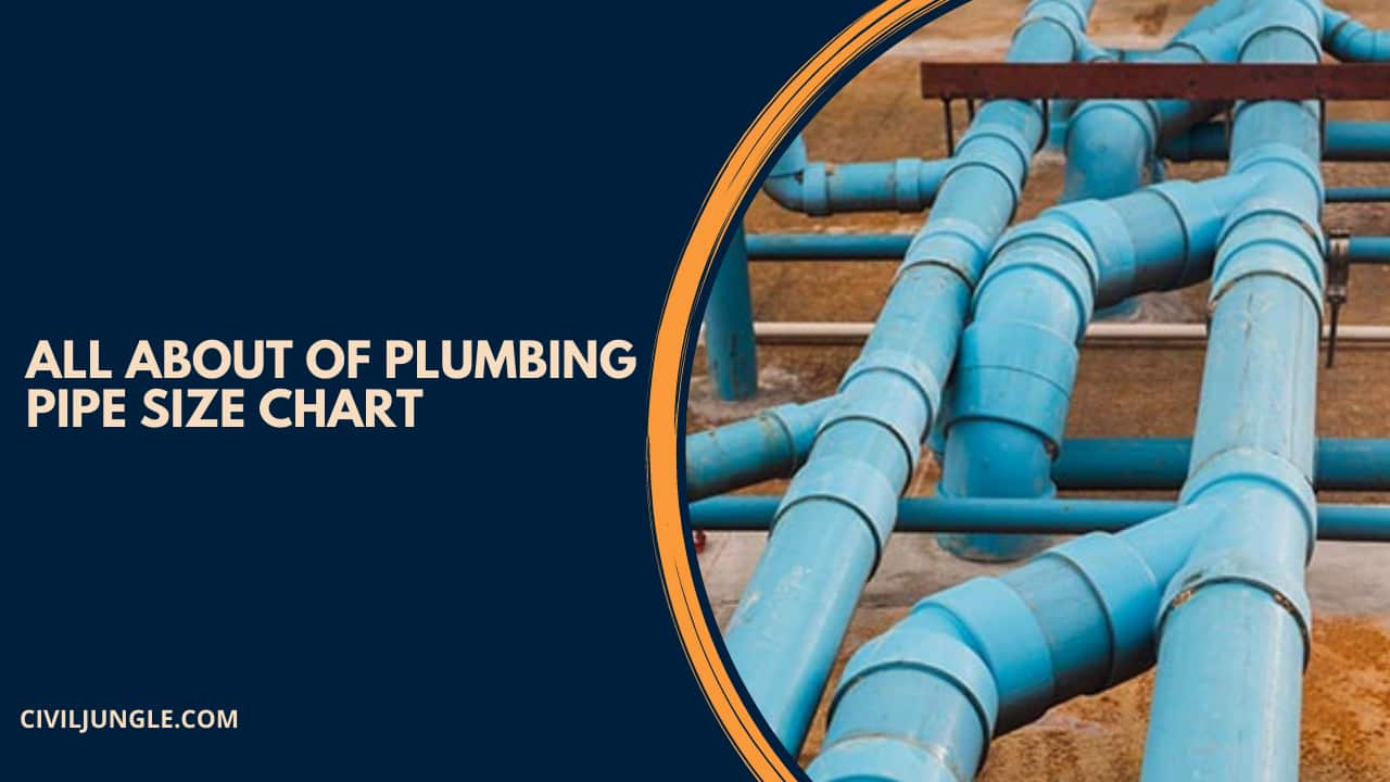
How to Determine Suitable Pipe Sizes for Water Supply in Building?
There are various points and factors which are responsible for determining the sizes for water supply. Pipes are generally available for different sizes, so the process of determining the suitable pipe is-
- The pipes have opted for water supply in the building according to the purpose of the building.
- The total cost of the building is also very important to point for choosing the pipe for water supply in the building.
- According to water pressure, the pipes are selected for a different building.
- According to the amount of water is also undertaken in selecting the pipes for water supply in the building.
Plumbing Pipe Dimensions
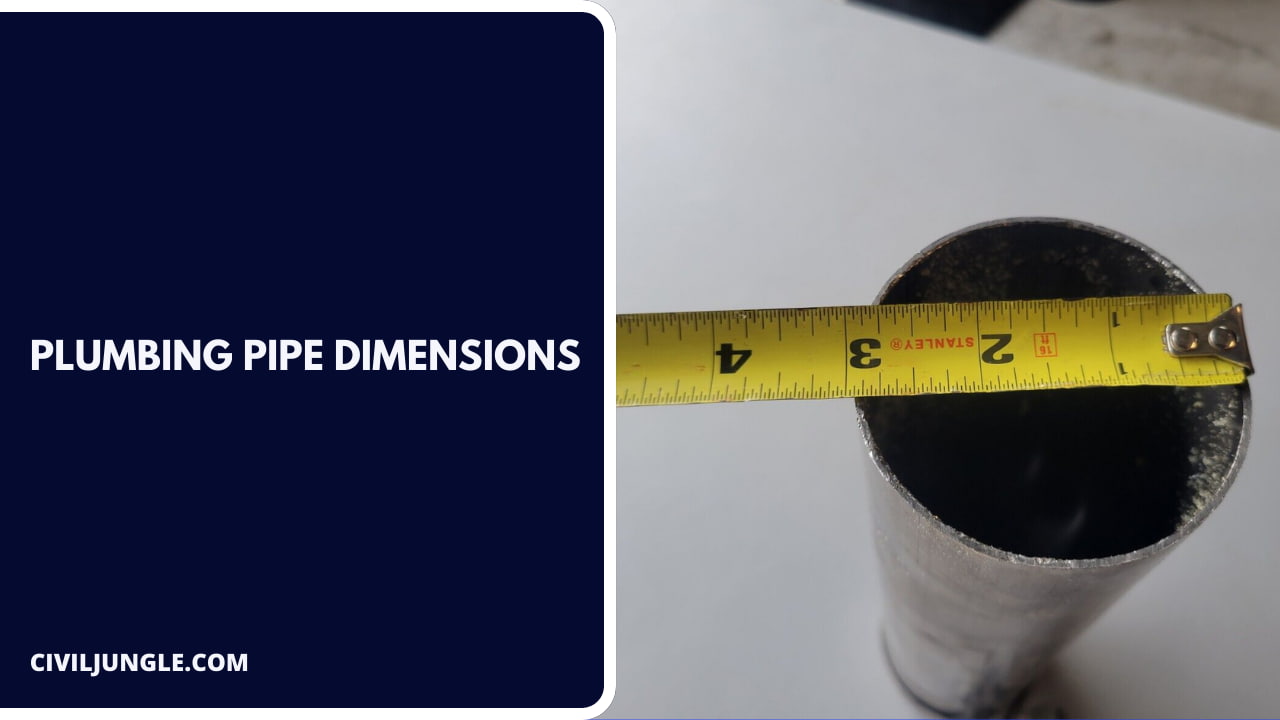
Plumbing pipes are generally made of PVC and steel. There are various sixes are available in the market, those are-
1. PVC Pipe Sizes
Here, the PVC pipe sizes details like outer diameter of the pipe, inside pipe dia., and wall thickness are as follows.
| NPS | Outside diameter of pipe (inch) | Inside diameter (inch) |
Wall Thickness (inch) |
| 1/8” | 0.405” | 0.269” | 0.068” |
| 1/4” | 0.540” | 0.364” | 0.088” |
| 3/8” | 0.675” | 0.493” | 0.091” |
| 1/2” | 0.840” | 0.622” | 0.109” |
| 3/4” | 1.050” | 0.824” | 0.113” |
| 1” | 1.315” | 1.049” | 0.133” |
| 1-1/4” | 1.660” | 1.380” | 0.140” |
| 1-1/2” | 1.900” | 1.610” | 0.145” |
| 2” | 2.375” | 2.067” | 0.154” |
| 2-1/2” | 2.875” | 2.469” | 0.203” |
| 3” | 3.500” | 3.068” | 0.216” |
| 4” | 4.500” | 4.026” | 0.237” |
| 5” | 5.563” | 5.047” | 0.258” |
| 6” | 6.625” | 6.065” | 0.280” |
| 8” | 8.625” | 7.981” | 0.322” |
| 10” | 10.750” | 10.020” | 0.365” |
| 12” | 12.750” | 11.938” | 0.406” |
| 14” | 14.000” | 13.126” | 0.437” |
| 16” | 16.000” | 15.000” | 0.500” |
| 18” | 18.000” | 16.876” | 0.562” |
| 20” | 20.000” | 18.814” | 0.593” |
| 24” | 24.000” | 22.626” | 0.687” |
2. Steel Pipe Sizes
Here, the steel pipe sizes details like outer diameter of the pipe, inside pipe dia., and wall thickness are as follows.
| NPS | Outside diameter (inch) |
Inside diameter (inch) | Wall thickness (inch) |
| 1/8 | .0405” | 0.215” | 0.095” |
| 1/4 | 0.540” | 0.302” | .0119” |
| 3/8 | 0.675” | 0.423” | 0.126” |
| 1/2 | 0.840” | 0.546” | 0.147” |
| 3/4 | 1.050” | 0.742” | 0.154” |
| 1 | 1.315” | 0.957” | 0.179” |
| 1-1/4 | 1.660” | 1.278” | 0.191” |
| 1-1/2 | 1.900” | 1.500” | 0.200” |
| 2 | 2.375” | 1.939” | 0.218” |
| 2-1/2 | 2.875” | 2.323” | 0.276” |
| 3 | 3.500” | 2.900” | 0.300” |
| 3-1/2 | 4.000” | 3.364” | 0.318” |
| 4 | 4.500” | 3.826” | 0.337” |
| 5 | 5.563”a | 4.813” | 0.375” |
| 6 | 6.625” | 5.761” | 0.432” |
| 8 | 8.625” | 7.625” | 0.500” |
| 10 | 10.750” | 9.562” | 0.594” |
| 12 | 12.75” | 11.374” | 0.688” |
| 14 | 14.000” | 12.500” | 0.750” |
| 16 | 16.000” | 14.312” | 0.844” |
| 18 | 18.000” | 16.124” | 0.938” |
| 20 | 20.000” | 17.938” | 1.031” |
| 24 | 24.000” | 21.562” | 1.219” |
Water Supply Line Size for Residential Building
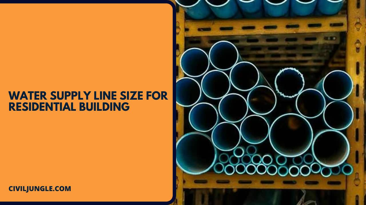
Water supply is one of the most important plumbing operations in any residential building. The size of pipes which are opted for residential buildings are.
| Individual Fixtures | Minimum Pipe Size (inch) | Private Home |
| Bar sink | ½” | 1.5 |
| Bathtub or shower | ½” | 4.0 |
| Cloth washer | ½” | 1.0 |
| Dishwasher | ½” | 1.5 |
| Hose bib | ½” | 2.5 |
| Hose bib additional | ½” | 1.0 |
| Kitchen sink | ½” | 1.5 |
| Laundry link | ½” | 2.0 |
| Bathroom sink | ½” | 1.0 |
| Shower | ½” | 2.0 |
| Toilet Gravity tank 1.6 | ½” | 2.5 |
| Toilet gravity tank 3.5> | ½” | 3.0 |
| Whirlpool bath | ½” | 4.0 |
Standard Plumbing Pipe Size
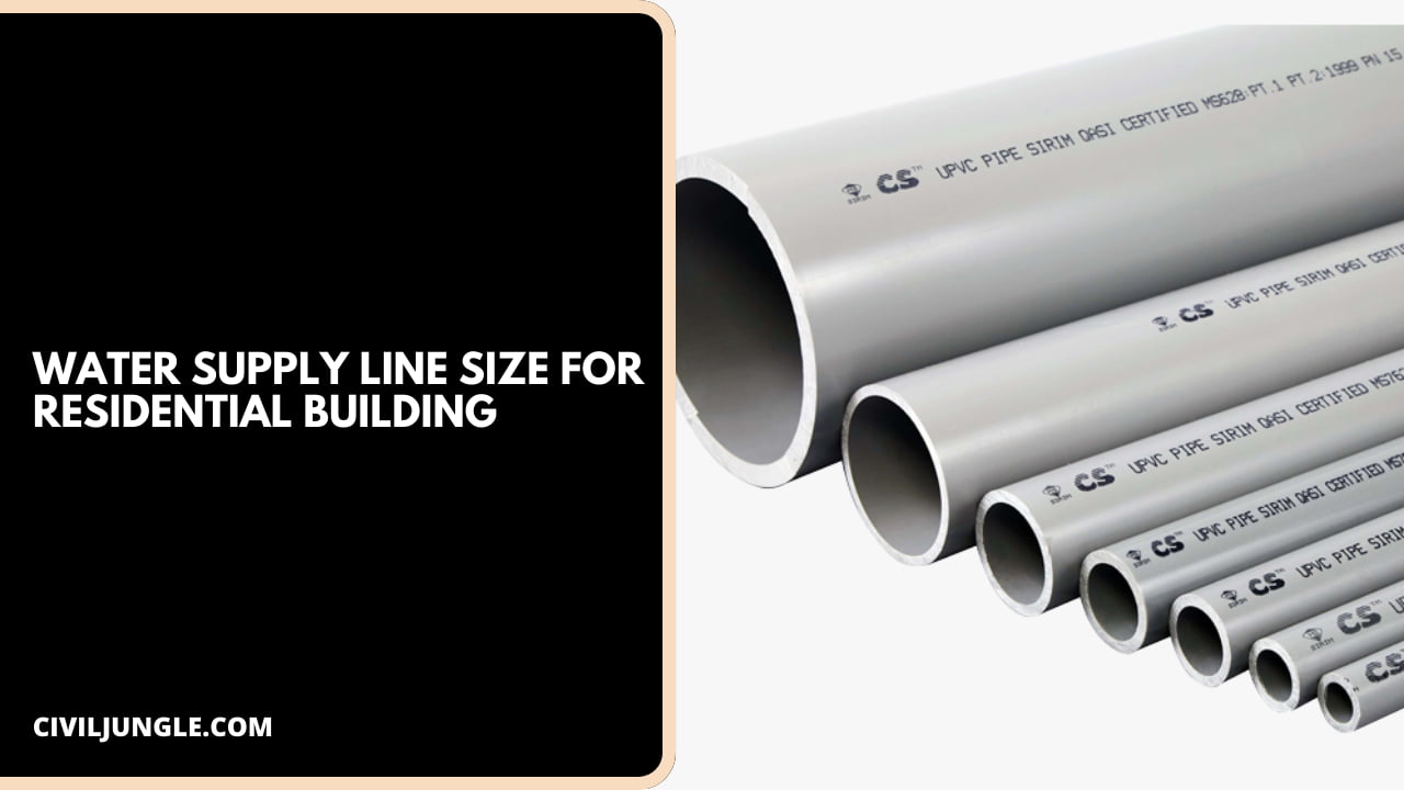
In a residential building, the standard dimension of pipe is 100 mm to 600 mm which have a thickness of 12 mm to 43 mm.
Factors Influencing Selection of Water Distribution Pipe Size in Building
There are many factors which are affecting the pipe size of the water distribution, those are.
- The main factor which are responsible for water distribution is the cost of the project.
- Water pressure is another criterion of the pie size selection.
- We need to keep in our mind that each property has different water pressure.
- Due to internal friction in the pipe, there are a loss of pressure happens. To overcome the loss of pressure we need to keep it into our mind.
- To avoid noise and pipe erosion we need to restrict the flow of water.
- Economical consideration is the another govern selection process for pipe selection. But many times we use most economical pipes.
Procedure of Determination of Pipe Sizes for Water Distribution in Buildings
Here, the procedure of determination of pipe size for water distribution in building are as follows.
- At first, we draw all the horizontal main lines, branch lines, and risers
- Then we calculate weight from table 1 and table 2
- Then we specify water demand in gallons per millimeter.
- After that, we estimate the equivalent length of pipe and this is starting from the main street line.
- Next, we determine the average minimum pressure in the main street line.
- Then we calculate the pressure loss in the pipes by using an equivalent length of pipe.
- After that, we finally choose the size of the pipe.
Fixture Units, Traps, and Connection Sizes for Plumbing Fixture for Dometic Waters.
Table 2: Domestic Water Fixture and Size of Pipe Requirement
|
Types of Water |
Domestic Water | |||
|
Fixture-Unit Value as Load Factors |
Minimum Size of Connections, mm |
|||
| Private | Public | Hot Water |
Cold Water |
|
| Bathtub (with or without overhead shower) | 2 | 4 | 12.7 | 12.7 |
| Bidet | ||||
| Combination sink and tray | 3 | – | 12.7 | 12.7 |
| Combination unit and tray with food disposal unit | 4 | |||
| Dental unit | 1 | 9.525 | ||
| Dental lavatory | 1 | 2 | 12.7 | 12.7 |
| Dish water, domestic | 2 | |||
| Drinking fountain | 1 | 2 | 9.525 | |
| Floor drains | 1 | |||
| Kitchen sink | 2 | 4 | 12.7 | 12.7 |
| Kitchen sink domestic with food waste grinder | 3 | |||
| Lavatory | 1 | 19.05 | 9.525 | |
| Lavatory | 2 | 12.7 | 12.7 | |
| Lavatory, beauty parlour, barber | 2 | |||
| Lavatory, surgeon’s | 2 | |||
| Laundry tray | 2 | 4 | 12.7 | 12.7 |
| Shower | 2 | 4 | 12.7 | 12.7 |
| Surgeon sink | 3 | 12.7 | 12.7 | |
| Sink (trap standard) | 3 | 12.7 | 12.7 | |
| Sink (P trap) | 2 | 4 | 12.7 | 12.7 |
| Urinal, pedestal, siphon jet | 10 | 12.7 | ||
| Urinal, wall lip | 5 | 12.7 | ||
| Urinal with flush tank | 3 | |||
| Wash sink | 2 | 12.7 | 12.7 | |
| Tank operated Water closet | 3 | 5 | 19.05 | |
| Valve operated water closet | 6 | 10 | 25.4 | |
Table 2: Drainage Water Fixture and Size of Pipe Requirement
|
Types of Fixture |
Drainage | |
| Fixture-Unit Value as Load Factors |
Minimum Size of Trap, mm |
|
| Bathtub | 2 | 38.1 |
| Bidet | ||
| Combination sink and tray | 2 | |
| Combination tray with food disposal unit | 3 | |
| Dental unit | 1 | 31.75 |
| Dental lavatory | 2 | |
| Dish water | 2 | 38.1 |
| Drinking fountain | 1 | 31.75 |
| Floor drains | 2 | 50.8 |
| Kitchen sink | 2 or 3 | 38.1 |
| Kitchen sink with waster grinder | 2 | |
| Lavatory | 1 | 31.75 |
| Lavatory | 2 | 38.1 |
| Beauty parlour, barber | 2 | |
| Surgeon lavatory | 2 | |
| Laundry tray | 2 | |
| Shower | 2 | 50.8 |
| Sink flushing with valve | 6 | 76.2 |
| Sink (trap standard) | 3 | |
| Sink (P trap) | 3 | 50.8 |
| Sink pot | 3 | 38.1 |
| Urinal, pedestal | 6 | 76.2 |
| Wall urinal | 2 | 38.1 |
| Urinal stall | 2 | 50.8 |
| Urinal with flush tank | 2 | 38.1 |
| Wash sink | 3 | |
| Water closet with tank | 4 | 76.2 |
| Valve operated water closet | 6 | |
Plumbing Pipe Sizing Chart
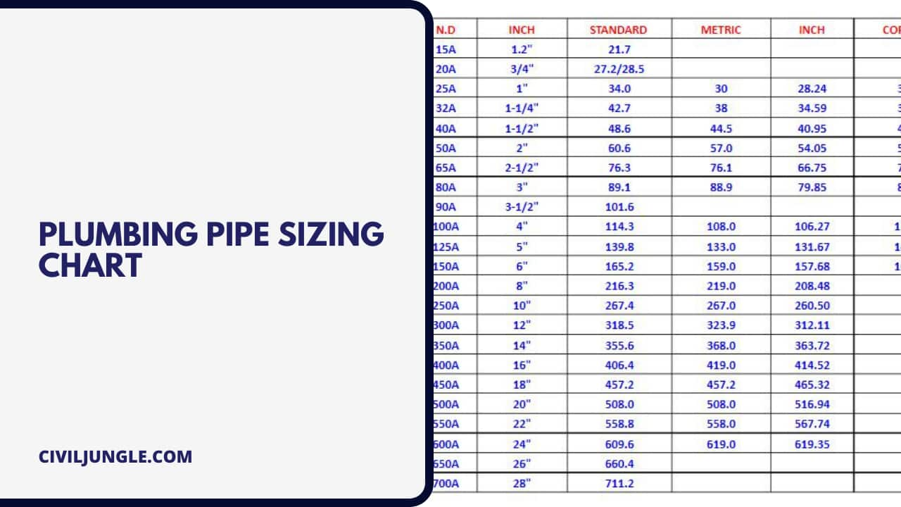
Here, the water pipe sizing chart are as follows.
| NPS | Outside diameter of pipe (inch) |
| 1/8” | 0.405” |
| 1/4” | 0.540” |
| 3/8” | 0.675” |
| 1/2” | 0.840” |
| 3/4” | 1.050” |
| 1” | 1.315” |
| 1-1/4” | 1.660” |
| 1-1/2” | 1.900” |
| 2” | 2.375” |
| 2-1/2” | 2.875” |
| 3” | 3.500” |
| 4” | 4.500” |
| 5” | 5.563” |
| 6” | 6.625” |
| 8” | 8.625” |
| 10” | 10.750” |
| 12” | 12.750” |
Kitchen Sink Drain Pipe Size
The most common size for modern sink drain pipes is 1 1/2 inches in diameter. However, there are also 2-inch and 3-inch pipes available. Some older sinks may have even smaller pipes like 1 1/4-inch in diameter.
The size of the drain pipe depends on the type of sink:
- Kitchen sink: 3 1/2 inches
- Bathroom sink: 1 1/4 inches
- Bar sink: 2 inches
- Toilets: 3 inches
- Washing machines and laundry sinks: 2 inches
- Showers and bathtubs: 1.5 inches
How to Find Standard Sewage Pipe Sizes?

Here, find standard sewage pipes size as per chart and calculation are as follows. The diagrams below can be used for the design of sewage and wastewater gravity conveying systems.
Sewage Pipe Capacity – Imperial units – gpm
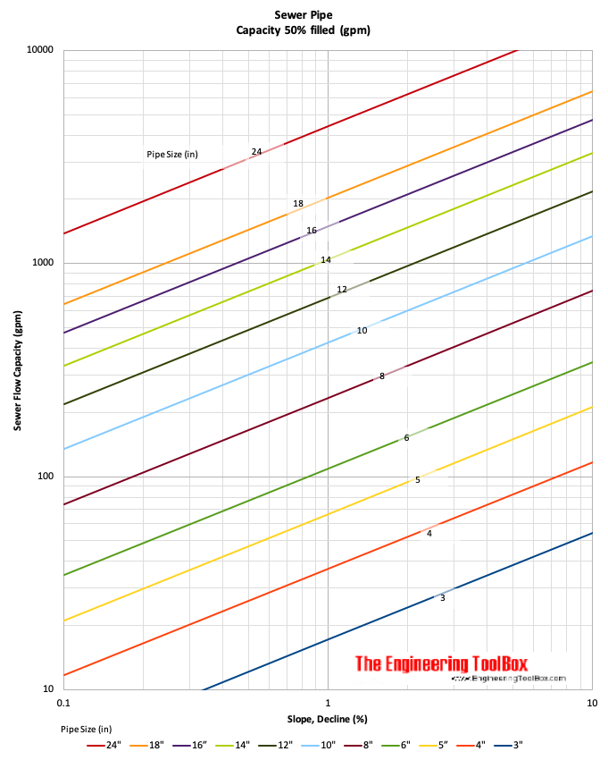
Sewer Pipe Sizing Chart
Credit: engineeringtoolbox.com
Note – the charts are based on clean plastic pipes – calculated with the Manning formula, roughness coefficient 0.015 and fill 50%.
Piping Sizing Calculation – Capacity of a Sewer Pipe
The capacity of an 8-inch sewer pipe with a decline of 0.5% is approx. 25 gpm (1.6 liter/s).
Decline and Slope
Calculate between decline and slope units
d = 8.33 s(in/ft)
d = 100 s(ft/ft)
d = 100 s(m/m)
d = s(ft/100ft)
where
d = decline (%)
s = slope
Example – % Decline
1/8 in/ft slope can be transformed to % decline as
d = 8.33 (1/8 in/ft)
d = 2.08 %
Water Pipe Sizing Chart
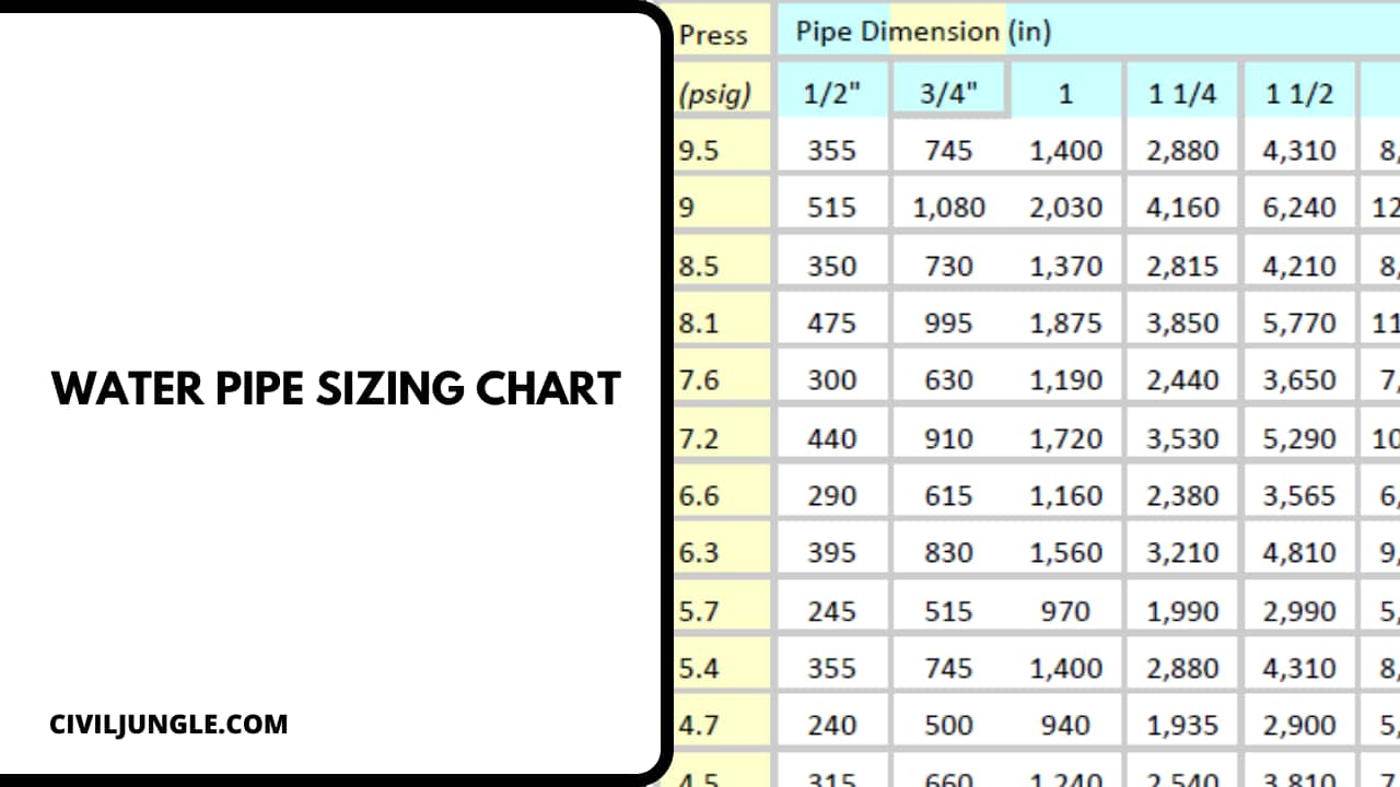
Here, the different types of water pipe size charts are as follows.
| Meter & Street Service (inches) | Building Supply & Branches (inches) | Maximum Allowable Length (feet) | ||||||||||||||
| 40 | 60 | 80 | 100 | 150 | 200 | 250 | 300 | 400 | 500 | 600 | 700 | 800 | 900 | 1000 | ||
| Pressure Range – 30 to 45 psi (available static pressure after head loss) | ||||||||||||||||
| 3/4 | 1/2 | 6 | 5 | 4 | 3 | 2 | 1 | 1 | 1 | 0 | 0 | 0 | 0 | 0 | 0 | 0 |
| 3/4 | 3/4 | 16 | 16 | 14 | 12 | 9 | 6 | 5 | 5 | 4 | 4 | 3 | 2 | 2 | 2 | 1 |
| 3/4 | 1 | 29 | 25 | 23 | 21 | 17 | 15 | 13 | 12 | 10 | 8 | 6 | 6 | 6 | 6 | 6 |
| 1 | 1 | 36 | 31 | 27 | 25 | 20 | 17 | 15 | 13 | 12 | 10 | 8 | 6 | 6 | 6 | 6 |
| 3/4 | 1-1/4 | 36 | 33 | 31 | 28 | 24 | 23 | 21 | 19 | 17 | 16 | 13 | 12 | 12 | 11 | 11 |
| 1 | 1-1/4 | 54 | 47 | 42 | 38 | 32 | 28 | 25 | 23 | 19 | 17 | 14 | 12 | 12 | 11 | 11 |
| 1-1/2 | 1-1/4 | 78 | 68 | 57 | 48 | 38 | 32 | 28 | 25 | 21 | 18 | 15 | 12 | 12 | 11 | 11 |
| 1 | 1-1/2 | 85 | 84 | 79 | 65 | 56 | 48 | 43 | 38 | 32 | 28 | 26 | 22 | 21 | 20 | 20 |
| 1-1/2 | 1-1/2 | 150 | 124 | 105 | 91 | 70 | 57 | 49 | 45 | 36 | 31 | 26 | 23 | 21 | 20 | 20 |
| 2 | 1-1/2 | 151 | 129 | 129 | 110 | 80 | 64 | 53 | 46 | 38 | 32 | 27 | 23 | 21 | 20 | 20 |
| 1 | 2 | 85 | 85 | 85 | 85 | 85 | 85 | 82 | 80 | 66 | 61 | 57 | 52 | 49 | 46 | 43 |
| 1-1/2 | 2 | 220 | 205 | 190 | 176 | 155 | 138 | 127 | 120 | 104 | 85 | 70 | 61 | 57 | 54 | 51 |
| 2 | 2 | 370 | 327 | 292 | 265 | 217 | 185 | 164 | 147 | 124 | 96 | 70 | 61 | 57 | 54 | 51 |
| 2 | 2-1/2 | 445 | 418 | 390 | 370 | 330 | 300 | 280 | 265 | 240 | 220 | 198 | 175 | 158 | 143 | 133 |
| Pressure Range – 46 to 60 psi (available static pressure after head loss) | ||||||||||||||||
| 3/4 | 1/2 | 7 | 7 | 6 | 5 | 4 | 3 | 2 | 2 | 1 | 1 | 1 | 0 | 0 | 0 | 0 |
| 3/4 | 3/4 | 20 | 20 | 19 | 17 | 14 | 11 | 9 | 8 | 6 | 5 | 4 | 4 | 3 | 3 | 3 |
| 3/4 | 1 | 39 | 39 | 36 | 33 | 28 | 23 | 21 | 19 | 17 | 14 | 12 | 10 | 9 | 8 | 8 |
| 1 | 1 | 39 | 39 | 39 | 36 | 30 | 25 | 23 | 20 | 18 | 15 | 12 | 10 | 9 | 8 | 8 |
| 3/4 | 1-1/4 | 39 | 39 | 39 | 39 | 39 | 39 | 34 | 32 | 27 | 25 | 22 | 19 | 19 | 17 | 16 |
| 1 | 1-1/4 | 78 | 78 | 76 | 67 | 52 | 44 | 39 | 36 | 30 | 27 | 24 | 20 | 19 | 17 | 16 |
| 1-1/2 | 1-1/4 | 78 | 78 | 78 | 78 | 66 | 52 | 44 | 39 | 33 | 29 | 24 | 20 | 19 | 17 | 16 |
| 1 | 1-1/2 | 85 | 85 | 85 | 85 | 85 | 85 | 80 | 67 | 55 | 49 | 41 | 37 | 34 | 32 | 30 |
| 1-1/2 | 1-1/2 | 151 | 151 | 151 | 151 | 128 | 105 | 90 | 78 | 62 | 52 | 42 | 38 | 35 | 32 | 30 |
| 2 | 1-1/2 | 151 | 151 | 151 | 151 | 150 | 117 | 98 | 84 | 67 | 55 | 42 | 38 | 35 | 32 | 30 |
| 1 | 2 | 85 | 85 | 85 | 85 | 85 | 85 | 85 | 85 | 85 | 85 | 85 | 85 | 85 | 83 | 80 |
| 1-1/2 | 2 | 370 | 370 | 340 | 318 | 272 | 240 | 220 | 198 | 170 | 150 | 135 | 123 | 110 | 102 | 94 |
| 2 | 2 | 370 | 370 | 370 | 370 | 368 | 318 | 280 | 250 | 205 | 165 | 142 | 123 | 110 | 102 | 94 |
| 2 | 2-1/2 | 654 | 640 | 610 | 580 | 535 | 500 | 470 | 440 | 400 | 365 | 335 | 315 | 285 | 267 | 250 |
| Pressure Range – over 60 psi (available static pressure after head loss) | ||||||||||||||||
| 3/4 | 1/2 | 7 | 7 | 7 | 6 | 5 | 4 | 3 | 3 | 2 | 1 | 1 | 1 | 1 | 1 | 0 |
| 3/4 | 3/4 | 20 | 20 | 20 | 20 | 17 | 13 | 11 | 10 | 8 | 7 | 6 | 6 | 5 | 4 | 4 |
| 3/4 | 1 | 39 | 39 | 39 | 39 | 35 | 30 | 27 | 24 | 21 | 17 | 14 | 13 | 12 | 12 | 11 |
| 1 | 1 | 39 | 39 | 39 | 39 | 38 | 32 | 29 | 26 | 22 | 18 | 14 | 13 | 12 | 12 | 11 |
| 3/4 | 1-1/4 | 39 | 39 | 39 | 39 | 39 | 39 | 39 | 39 | 34 | 28 | 26 | 25 | 23 | 22 | 21 |
| 1 | 1-1/4 | 78 | 78 | 78 | 78 | 74 | 62 | 53 | 47 | 39 | 31 | 26 | 25 | 23 | 22 | 21 |
| 1-1/2 | 1-1/4 | 78 | 78 | 78 | 78 | 78 | 74 | 65 | 54 | 43 | 34 | 26 | 25 | 23 | 22 | 21 |
| 1 | 1-1/2 | 85 | 85 | 85 | 85 | 85 | 85 | 85 | 85 | 81 | 64 | 51 | 48 | 46 | 43 | 40 |
| 1-1/2 | 1-1/2 | 151 | 151 | 151 | 151 | 151 | 151 | 130 | 113 | 88 | 73 | 51 | 51 | 46 | 43 | 40 |
| 2 | 1-1/2 | 151 | 151 | 151 | 151 | 151 | 151 | 142 | 122 | 98 | 82 | 64 | 51 | 46 | 43 | 40 |
| 1 | 2 | 85 | 85 | 85 | 85 | 85 | 85 | 85 | 85 | 85 | 85 | 85 | 85 | 85 | 85 | 85 |
| 1-1/2 | 2 | 370 | 370 | 370 | 370 | 360 | 335 | 305 | 282 | 244 | 212 | 187 | 172 | 153 | 141 | 129 |
| 2 | 2 | 370 | 370 | 370 | 370 | 370 | 370 | 370 | 340 | 288 | 245 | 204 | 172 | 153 | 141 | 129 |
| 2 | 2-1/2 | 654 | 654 | 654 | 654 | 654 | 650 | 610 | 570 | 510 | 460 | 430 | 404 | 380 | 356 | 329 |
Water Pipe Sizing Chart Fixture Units
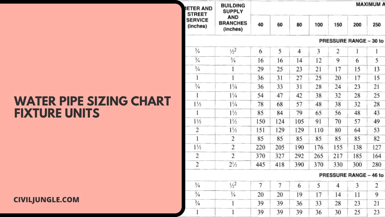
Here, the water pipe sizing chart fixture units are as follows.
| Sr.No. | Appliances, Appurtenances, or Fixtures | Minimum Fixture Branch Pipe Size (inches) | Private | Public |
| 1 | Bathtub or Combination Bath/Shower | 1/2 | 4 | 4 |
| 2 | 3/4″ Bathtub Fill Valve | 3/4 | 10 | 10 |
| 3 | Bidet | 1/2 | 1 | — |
| 4 | Clothes Washer | 1/2 | 4 | 4 |
| 5 | Dental Unit, Cuspidor | 1/2 | — | 1 |
| 6 | Dishwasher, Domestic | 1/2 | 1.5 | 1.5 |
| 7 | Drinking Fountain or Water Cooler | 1/2 | 0.5 | 0.5 |
| 8 | Hose Bibb | 1/2 | 2.5 | 2.5 |
| 9 | Hose Bibb, Each Additional | 1/2 | 1 | 1 |
| 10 | Lavatory | 1/2 | 1 | 1 |
| 11 | Lawn Sprinkler, Each Head | — | 1 | 1 |
| 12 | Mobile Home, Each (minimum) | — | 12 | — |
| 13 | Bar Sink | 1/2 | 1 | 2 |
| 14 | Clinic Faucet SInk | 1/2 | — | 3 |
| 15 | Clinic Flushometer Valve Sink (with or without faucet) | 1 | — | 8 |
| 16 | Kitchen Sink, Domestic (with or without dishwasher) | 1/2 | 1.5 | 1.5 |
| 17 | Laundry Sink | 1/2 | 1.5 | 1.5 |
| 18 | Service Sink or Mop Basin | 1/2 | 1.5 | 1.5 |
| 19 | Washup Sink (each set of faucets) | 1/2 | — | 2 |
| 20 | Shower, Per Head | 1/2 | 2 | 2 |
| 21 | Urinal, Flush Tank | 1/2 | 2 | 2 |
| 22 | Wash Fountain (circular spray) | 3/4 | — | 4 |
| 23 | Water Closet, 1.6 GPF Gravity Tank | 1/2 | 2.5 | 2.5 |
| 24 | Water Closet, 1.6 GPF Flushometer Tank | 1/2 | 2.5 | 2.5 |
| 25 | Water Closet, Greater Than 1.6 GPF Gravity Tank | 1/2 | 3 | 5.5 |
Water Pipe Sizing Chart PDF: Click Here
Plumbing Pipe Sizing
Here, the water supply pipe sizing as per useing water temp. are as follows.
| Minimum Pipe Diamater | ||
| Water Temp | Cold | Host |
| Toilet | 3/8″ | – |
| Bathtub | 1/2″ | 1/2″ |
| Lavatory (sink) | 3/8″ | 3/8″ |
| Shower | 1/2″ | 1/2″ |
| Bar sink | 3/8″ | 3/8″ |
| Kitchen sink | 1/2″ | 1/2″ |
| Bar sink | 3/8″ | 3/8″ |
| Dishwasher | – | 3/8″ to 1/2″ |
| Washing machine | 1/2″ | 1/2″ |
| Laundry sink | 1/2″ | 1/2″ |
| Water heater | 3/4″ | – |
| Hose bibb | 1/2″ to 3/4″ | – |
Domestic Water Pipe Sizing
Here, the water supply pipe sizing as per useing water temp. are as follows.
| Fixture | Minimum Pipe Size (in.) | Flow Rate (GPM) | Pressure (psi) |
| Drinking Fountain | 5/8″ | 4 | 8 |
| Bathtub | 1/2″ | 2.75 | 8 |
| Lavatory (sink) | 3/8″ | 0.75 | 8 |
| Shower | 1/2″ | 5,15 | 8,15 |
| Kitchen sink | 1/2″ | 2.5 | 8 |
| Laundry | 1/2″ | 4 | 8 |
| Hose bibb | 1/2″ Int, 3/4″ Ext | 2 | 8 |
| Service Sink | 1/2″ | 3 | 8 |
| Urinal Flush Valve | 3/4″ | 1.6 | 15 |
| Water Closet Tank | 3/8″ | 1.6 | 15 |
| Water Closet Valve | 1″ | 1.6 | 15 |
IPC Water Pipe Sizing
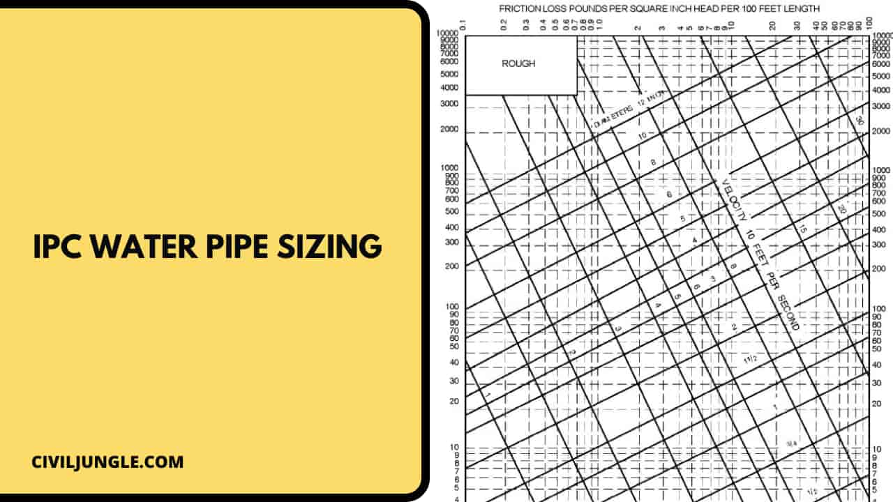
Here, the IPC water pipe sizing for fixtures are as follows.
| Fixture (Source IPC) | Cold | Hot | Total |
| Bidet, Private | 1.5 | 1.50 | 2.00 |
| DishWash-Private | 0.00 | 1.40 | 1.40 |
| Drinking Fountain | 0.25 | 0.00 | 0.25 |
| Kitchen Sink, Public | 3.00 | 3.00 | 4.00 |
| Kitchen Sink, Private | 1.00 | 1.00 | 1.40 |
| Laundry Tray, Private | 1.00 | 1.00 | 1.40 |
| Lav, Private | 0.50 | 0.50 | 0.70 |
| Lav, Public | 1.50 | 1.50 | 2.00 |
| Service Sink | 2.25 | 2.25 | 3.00 |
| Shower, Private | 1.00 | 1.00 | 1.40 |
| Shower, Public | 3.00 | 3.00 | 4.00 |
| Urinal, Priv, Flush | 10.00 | 0.00 | 10.00 |
| Urinal, 3/4” Priv, Flush | 5.00 | 0.00 | 5.00 |
| Urinal, Public, Tank | 3.00 | 0.00 | 3.00 |
| Wash Mach Lg, Pub | 3.00 | 3.00 | 4.00 |
| Wash Mach Sm, Pub | 2.25 | 2.25 | 3.00 |
| Wash Mach Sm, Pri | 1.00 | 1.00 | 1.40 |
| WC, Pri, Tank | 2.20 | 0.00 | 2.20 |
| WC, Pri, Flush | 6.00 | 0.00 | 6.00 |
| WC, Pub, Tank | 5.00 | 0.00 | 5.00 |
| WC, Pub, Flush | 10.00 | 0.00 | 10.00 |
| Bathroom group, private, flush tank | 2.70 | 1.50 | 3.60 |
| Bathroom group, private, flush valve | 6.00 | 3.00 | 8.00 |
| Bathtub, private, faucet | 1.00 | 1.00 | 1.40 |
| Bathtub, public, faucet | 3.00 | 3.00 | 4.00 |
| Combination fixture, private, faucet | 2.25 | 2.25 | 3.00 |
Water Supply Line Size Calculation
There are three steps to calculating the proper size for a plumbing piping system: Add up the total number of water supply fixture units (wsfu) required in the facility.
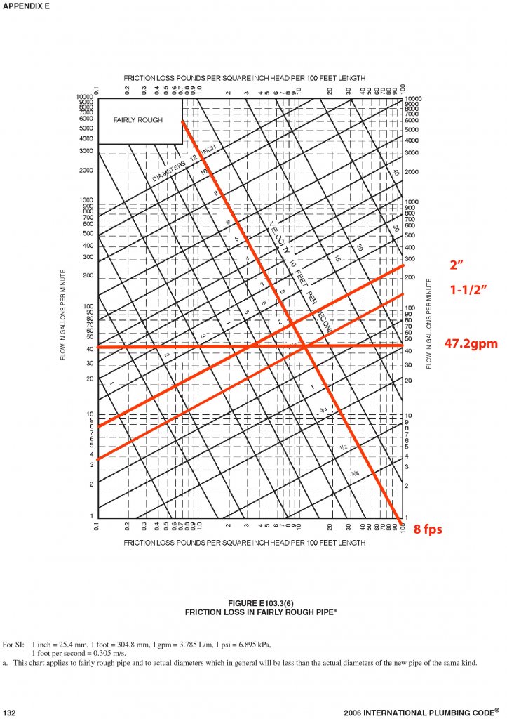
Estimate demand using the table from the IPC that correlates wsfu to expected demand. Size the pipe using demand vs friction loss curves found in the IPC chart.
Example: Domestic cold water for a public bathroom with four flush valve water closets and two lavatories. You can tell by using the ipc chart (see figure 1) that the wsfu values are 10 for the water closets and 1.5 each for the lavatories.
The total wsfu required is calculated like this:
- WCs: 4 X 10 wsfu = 40 wsfu
- 2 Lavs: 2 X 1.5 wsfu = 3 wsfu
- Total wsfu: 40 + 3 = 43
Demand =48−(48−46)∗(45−43)(45−40)
Demand =47.2 Gpm
FAQ: Optimizing Pipe Sizes for Building Water Supply
Why Is Pipe Size Important in a Building’s Water Supply System?
Pipe size affects the efficiency of water delivery, pressure maintenance, and overall system performance. Proper sizing ensures adequate water flow, minimizes pressure loss, and reduces the risk of pipe damage or water hammer.
How Do I Determine the Correct Pipe Size for Different Applications?
The correct pipe size is determined by factors such as the water demand, flow rate, and pressure requirements. Guidelines provided by building codes, hydraulic calculations, and professional recommendations should be followed to select the appropriate pipe size.
What Factors Should Be Considered When Sizing Pipes for a Building’s Water Supply?
Key factors include the building’s water demand, the length of the pipe runs, the type of fixtures, and the pressure available from the municipal supply. Additionally, the pipe material and potential future expansions should be considered.
How Can Incorrect Pipe Sizing Affect a Building’s Water System?
Incorrect pipe sizing can lead to issues such as low water pressure, reduced flow rate, noise from water hammer, and increased risk of pipe bursts. Over-sized pipes may also lead to increased costs and inefficient system performance.
What Are the Common Methods Used for Calculating Pipe Sizes?
Common methods include using pipe sizing charts, performing hydraulic calculations, and applying formulas such as the Hazen-Williams equation for water flow. Consulting with a plumbing engineer or using specialized software can also aid in accurate sizing.
Can Pipe Size Be Adjusted After Installation If Problems Arise?
Adjusting pipe size after installation can be challenging and costly. It is best to ensure proper sizing during the design phase. However, if issues arise, retrofitting or replacing sections of the pipe may be necessary.
How Do Building Codes Influence Pipe Sizing?
Building codes provide minimum requirements for pipe sizes based on factors such as building type, water demand, and safety standards. Adhering to these codes ensures compliance and optimal performance of the water supply system.
What Role Does Pipe Material Play in Sizing Decisions?
Different pipe materials have varying flow characteristics and pressure ratings. The choice of material can influence pipe size requirements and should be considered alongside other factors such as durability and cost.
Are There Any Best Practices for Maintaining Optimal Pipe Size in a Water Supply System?
Best practices include regular maintenance and inspections, avoiding excessive pipe lengths, ensuring proper installation, and considering future water demand when designing the system. Consulting with professionals can help maintain optimal performance.
Where Can I Get Professional Help with Pipe Sizing for My Building?
Professional help can be obtained from plumbing engineers, mechanical engineers, or specialized plumbing contractors. They can provide expertise in designing, calculating, and installing the appropriate pipe sizes for your building’s water supply system.

