Introduction of Gantry Girder
The gantry girders are girders which supports the loads that are transmitted through the travelling wheels of the crane. The crane girder spans from column to column, this usually do not have any lateral support at the intermediate points excepting when a walkway is formed at the top of the girder.
Overhead traveling cranes are used in industrial buildings to lift and transport heavy jobs, machines, and so on, from one place to another. The crane may be a manually (hand) operated overhead traveling crane (M.O.T.) or an electrically operated overhead traveling crane (E.O.T.).
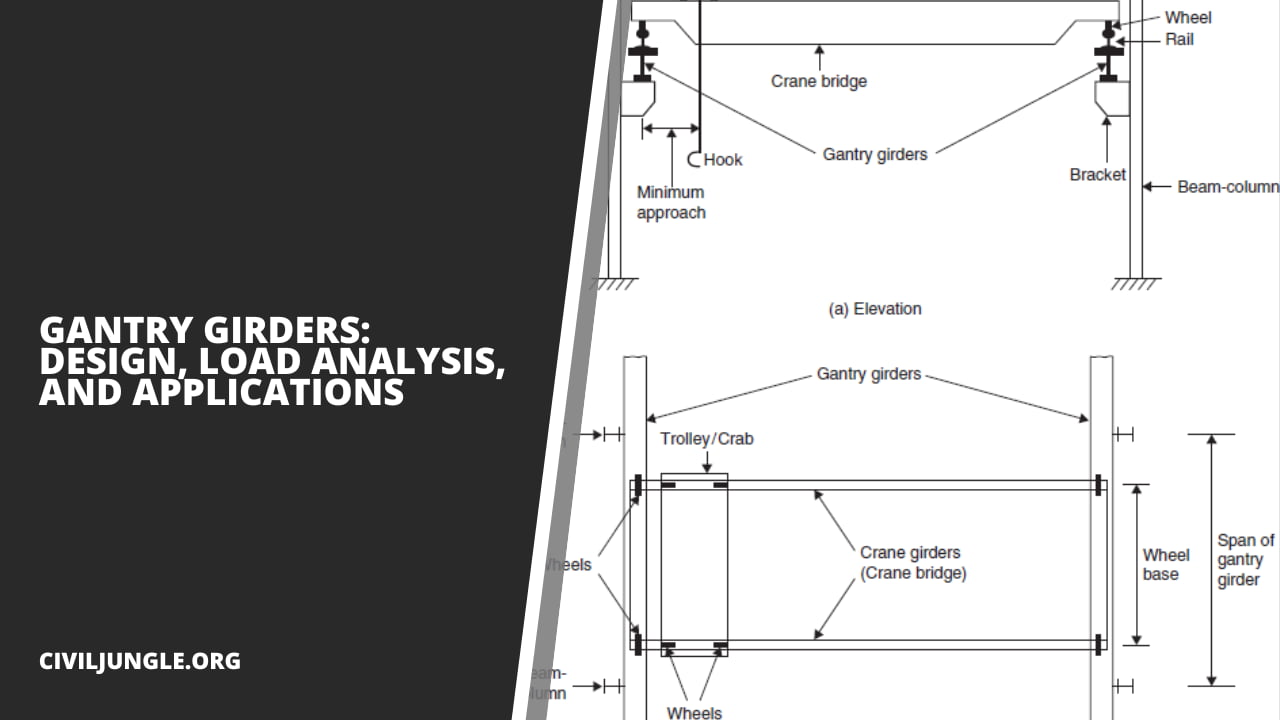
A typical arrangement of a crane system is shown below. Usually, the crane consists of a bridge made up of two truss girders. The bridge is termed a crane bridge, crane girder, or crab girder. It spans the bay of the shop and moves in a longitudinal direction.
To facilitate movement, wheels are attached to the ends of crane girders. These wheels move over rails placed centrally over the girders which are called gantry or crane gantry girders.
These girders are designed as laterally unsupported beams until the compression flange is laterally supported by either a catwalk or by an additional member. Show below fig. the front view and top view of the typical arrangement of a crane girder, gantry girder, and column in a workshop.

Fig. 2 Typical Arrangement of Gantry Girder and Crane Girder
A trolley (crab) with wheels and a suspended hook is placed over the crane bridge and this arrangement can move in the transverse direction. However, it should be noted that the two movements of the crane, the longitudinal and the transverse cannot be had simultaneously. Bolted clamps or hook bolts are, used to keep the rails in position.

Fig 3. Gantry Girder Concocted With Bolted Clamp

Fig 4. Gantry Girder Concocted With Hook bolt
The gantry girders, because of the necessary clearances, must be placed a distance away from the face of columns. A direct connection with the column, therefore, is impossible. Because of lateral loads, however, some types of connection is mandatory. This is provided by diaphragm as shown in Fig.2 (a).
In gantry girders, even when deflection is held within limits, there is some rotation at the ends under moving crane. Accordingly, some provision for longitudinal movement of the top flange at the ends must be made. This is usually taken care of by using bolts with slotted holes (Fig. 2(a), Fig 5.).

Fig 5. Gantry Girder I Section
Some of the types of sections used for gantry girders are shown in Fig. 3,4,5,6 . An I-Section is provided for a manually operated overhead crane (Fig. 3).
The top flange of the I-section is reinforced with a channel with its flanges turned down on the compression flange (Fig. 4) or a channel and a bracket plate are attached to the web of the I-section (Fig. 5) to increase the lateral resistance against the horizontal surge from electrically operated overhead traveling cranes as well as torsional rigidity.
If required, still heavier sections as shown in Fig. 6, may be provided.

Fig 5. Gantry Girder Havioe Section
Load on Gantry Girder
Gantry girders are unique in themselves. First, it is different from the usual beams in buildings. It is laterally unsupported except at the columns. Second, it is one of the very few girders in the buildings that are subjected to impact. Third, it must be analyzed for unsymmetrical bending because of lateral thrust from the starting and stopping of crab.
Fourth, it is subjected to longitudinal load due to starting and stopping of the crane bridge itself; and the fifth, these are always simply supported. These are subjected to the forces as follows.
1. The reaction from the crane girder, acting vertically downwards (Ref. Fig. 6).
2. The longitudinal thrust, due to the starting or stopping of a crane, acting in the longitudinal direction.
3. The lateral thrust, due to starting/stopping of the crab acting horizontally, normal to the gantry girder.
Types of Load on Gantry Girder:
- Vertical Loads on Gantry Girder.
- Lateral Loads on Gantry Girder.
- Longitudinal Loads on Gantry Girder.
- Impact Loads on Gantry Girder.
#1. Vertical Loads on Gantry Girder
A vertical load acting over the gantry girder is the reaction from the crane girder and consists of the self-weight of the crane, self-weight of the crab, and the crane capacity (the maximum load that can be hoisted).
To calculate the reaction the maximum wheel load is computed. It occurs when the crab is nearest to the gantry girder. In addition to the reaction from a crane girder, the self-weight of the rail should also be considered.
#2. Lateral Loads on Gantry Girder
Lateral forces on crane girders may be induced by the,
2.1. Thrust due to the sudden stopping of the crab and load when traversing the crab girders.
- As with the longitudinal gantry girders, the frictional resistance of the rail is transferred into the crab girders and from them into the crosshead girders, thence, as point loads through the main wheels, into the top or compression flanges of the gantry girders.
- The positions of the main wheels when maximum lateral bending and shear take place on the gantry girder will be the same as those when maximum vertical bending moment and shear occurs.
2.2. Crab dragging weights across the shop floor.
- The crane is often requisitioned to drag weights across the shop floor. If the load is extremely massive, it is usually mounted on roughly fashioned rollers, probably running on a timber plank track.
- The lateral thrust and pull on the compressive flanges of the gantry girders then become a matter of conjecture.
- The resisting forces are, firstly, the friction of the main wheel treads upon the gantry rails and, secondly, the forces offered by the flanges of the main wheels bearing against the gantry rails.
- The lateral thrust is assumed to act in the plane of the center of gravity of the upper flange. Acting as it does at the rail level, it has really a lever arm producing torque.
- This small lever arm and, therefore, the torque are neglected. No help is assumed to be afforded by the lower or tensile flange in resisting lateral thrust.
- However, should this help be considered, then the torque due to the thrust multiplied by the distance from the line of action of the thrust to the N.A. (n in this case)—should also be taken into consideration.
#3. Longitudinal Loads on Gantry Girder
Longitudinal loads are caused due to the stopping or starting of the crane girders and produce a thrust along the rails. The largest of these, especially in quick-acting electric overhead traveling cranes, is due to the sudden application of the brakes.
The frictional resistance to the sliding of the locked wheels upon the rails is supplied by the crane girder. This element in turn distributes it amongst all the crane column shafts. The lateral and longitudinal thrusts are transferred at the rail level. Therefore, gantry girders are also subjected to bending moments due to these loads.
#4. Impact Loads on Gantry Girder
The stresses produced in gantry girders due to the above loads are more than those caused by gradually applied loads. This is due to the forces set up by the sudden application of brakes to the rapidly moving loaded cranes acceleration, retardation, vibration, possible slip of slings, etc.
The steelwork which carries these quick-acting cranes must be heavier than the steelwork which supports slow-moving cranes.
With quick-acting electric overhead traveling (E.O.T) cranes, the stresses in the gantry girders are produced almost instantaneously, whereas with slow-moving hand-operated cranes, the bending stresses in the girder are induced gradually from zero up to their maximum values, as the cranes traverse the girder from the end towards the center.
| Types of Load | Additional Load |
| (a) Vertical forces transferred to the rails | |
| i. For electric operated cranes | 25 % of maximum static wheel load |
| ii. For hand-operated cranes | 10 % of the maximum static wheel load |
| (b) Horizontal forces are transverse to the rails. | |
| i. For electric operated cranes | 10 % of the weight of the crab and the weight lifted on the crane. |
| ii. For hand-operated cranes | 5 % of the weight of the crab and the weight lifted on the crane. |
| (C) Horizontal forces along the rails | 5 % of the static wheel load |
Additional Loads for Structures Subjected to Impact Load
To account for this, suitable impact factors are introduced as and when applicable. As per I.S: 875-1964, additional loads as listed in the above table should be considered when structures are subjected to impact loads in addition to live loads.
FAQs about Gantry Girders
What Is a Gantry Girder?
Gantry girders are structural beams that support the loads transmitted through the traveling wheels of a crane. They span from column to column in industrial buildings and are typically used to lift and transport heavy loads.
What Types of Cranes Are Used with Gantry Girders?
Gantry girders are used with both manually operated overhead traveling cranes (M.O.T.) and electrically operated overhead traveling cranes (E.O.T.).
How Are Gantry Girders Supported?
Gantry girders are designed as laterally unsupported beams, except at the columns. They may have additional support from a catwalk or other structural elements.
What Are the Different Types of Loads That Act on Gantry Girders?
The loads on gantry girders include vertical loads, lateral loads, longitudinal loads, and impact loads. These loads are caused by the weight of the crane, the movement of the crane and crab, and the forces due to starting and stopping.
How Are Vertical Loads on Gantry Girders Calculated?
Vertical loads include the reaction from the crane girder, the self-weight of the crane, the self-weight of the crab, and the maximum load the crane can hoist. The maximum wheel load is computed when the crab is nearest to the gantry girder.
What Causes Lateral Loads on Gantry Girders?
Lateral loads are caused by the thrust due to the sudden stopping of the crab and load, as well as the crane’s requirement to drag weights across the shop floor.
What Are Longitudinal Loads on Gantry Girders?
Longitudinal loads result from the stopping or starting of the crane girders, producing a thrust along the rails. These loads are significant in quick-acting electric overhead traveling cranes.
How Do Impact Loads Affect Gantry Girders?
Impact loads are caused by the forces set up due to the sudden application of brakes, acceleration, retardation, vibration, and possible slip of slings. These loads require the steelwork supporting quick-acting cranes to be heavier than that for slow-moving cranes.
What Sections Are Commonly Used for Gantry Girders?
Common sections for gantry girders include I-sections, which may be reinforced with channels or bracket plates to increase lateral resistance and torsional rigidity.
How Are Gantry Girders Connected to Columns?
Due to the necessary clearances, gantry girders are usually not directly connected to columns. Instead, connections are provided by diaphragms, and provisions for longitudinal movement of the top flange at the ends are made using bolts with slotted holes.
What Is the Purpose of Bolted Clamps and Hook Bolts in Gantry Girders?
Bolted clamps and hook bolts are used to keep the rails in position on the gantry girders, ensuring the proper functioning and stability of the crane system.
What Additional Loads Should Be Considered for Structures Subjected to Impact Loads?
As per I.S: 875-1964, additional loads include 25% of the maximum static wheel load for electric-operated cranes, 10% for hand-operated cranes, and horizontal forces based on the weight of the crab and the weight lifted.