What Is Blueprints Symbols?
Blueprints are basically the combination of some symbols. Blueprints symbols are used to indicate objects, functions or systems in the plan of engineering drawing.
Blueprints symbols are generally used in architectural drawing, structural drawing, electrical drawing, etc.
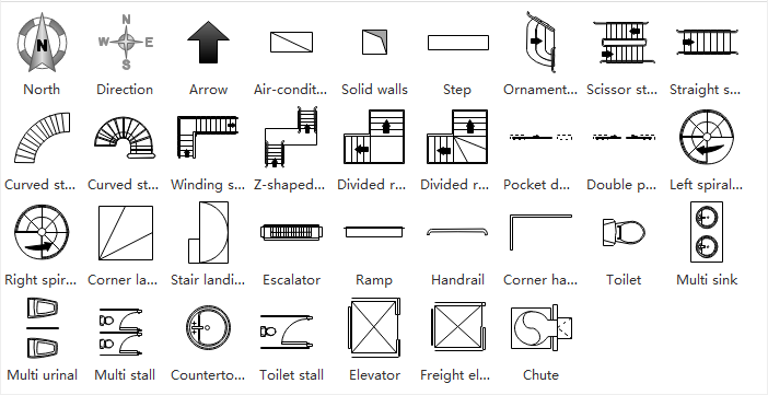
Floor Plan Symbols
Floor plan symbols are basically looking down from the top of the house. In-floor plans we found this type of symbols, it includes furniture, windows, doors, etc.
Some common symbols of floor plans are compass, doors, stairs, windows, walls, applications.
- Compass: It is basically an arrow symbol that gives orientation to the building by which the architect or builder can easily understand the north direction.By this symbol, we can easily detect east, west, north, south directions.
- Doors: Door symbol is presented by the straight line and the arc shows the opening projection of the door.
- Stairs: It is basically drawn by parallel lines which is generally located between two windows.
- Windows: The symbol of window is basically denoted by three lines.
- Walls: Walls are generally two types; interior walls and exterior walls. Both walls are drawn by two parallel lines but exterior wall lines are dark, thick and interior wall lines are light.
- Appliances: These are basically the other symbols in floor plan which are bathtub, toilet, sinks, other furniture, etc. All appliances symbols are drawn by single lines.
Some floor plan abbreviations.
- B- Beam
- AC- Air Conditioner
- BV- Butterfly Valve
- BC- Bookcase
- CBD- Cupboard
- CAB- Cabinet
- CL- Closet
- CF- Concrete Floor
- COL- Column
- CT- Ceramic Tile
- CW- Cavity Wall
- DS- Downspout
- EF- Exhaust Fan
- DW- Dish Washer
- GM- Gas Meter
- HTR- Heater
HVAC Symbols on Blueprints
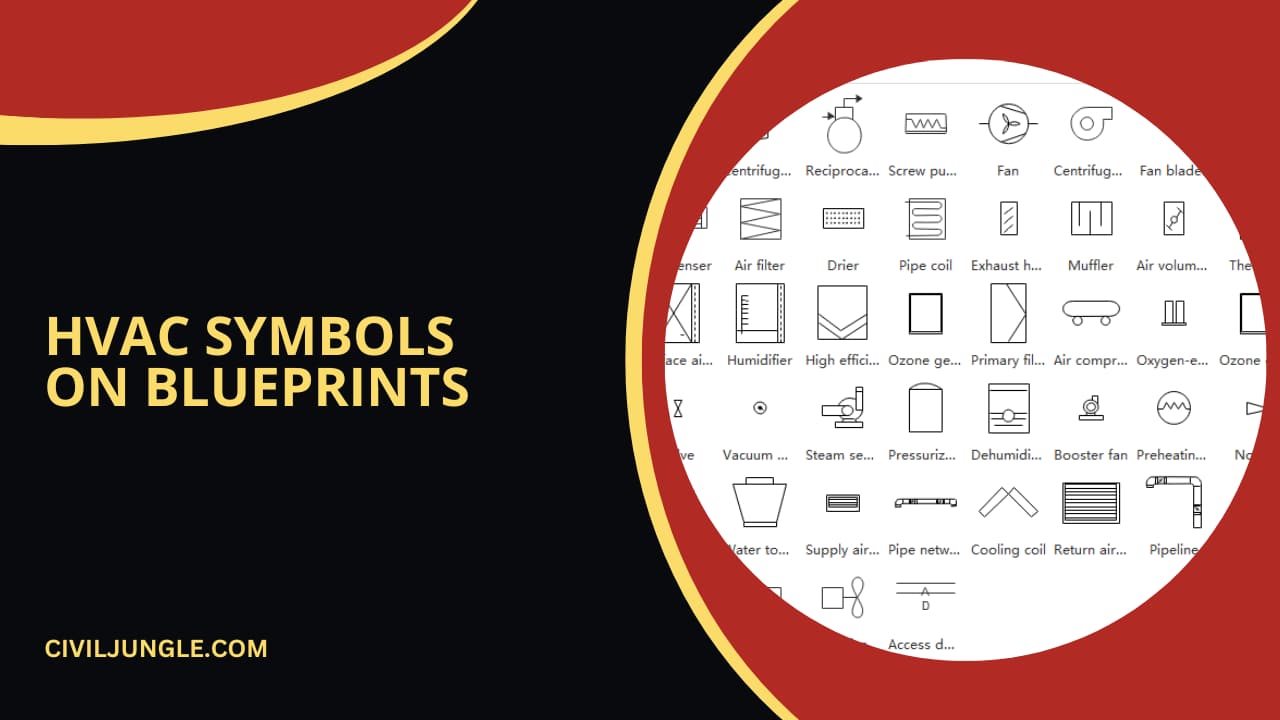
The full form of HVAC is heating, ventilation and air conditioning; these symbols are compacted in one place.
These symbols are generally denoted vents of AC, outside part of the building, etc. HVAC symbols are containing some symbols like wall vents, furnaces, ceiling vents, etc.
Some HVAC symbols are below-
| Sr.No. | HVAC Symbols on Blueprints | Symbols |
| 1 | Heater |  |
| 2 | Air Filter |  |
| 3 | Air Conditioner |  |
| 4 | Return Air Vent | 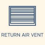 |
| 5 | Fan |  |
| 6 | Straight Duct | 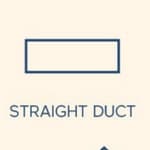 |
| 7 | Condenser | 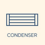 |
| 8 | Y Junction Duct | 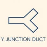 |
Plumbing And Piping Blueprint Symbols
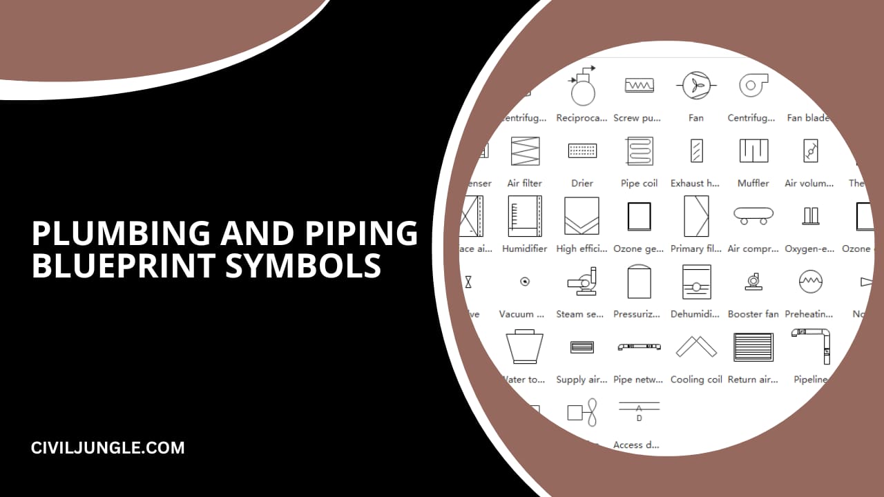
In any type of construction project, plumbing blueprint symbols is one of the most important departments.
In plumbing, if we talk about piping, then there have a commercial, residential and industrial piping system, by nature of the project this type of piping system is categorized.
Used in manufacturing processes in industrial projects the piping is designed for transferring gas and liquid.
On the other hand in commercial and residential projects, the piping system is provided just for water supply, and the freshwater is used for drinking purposes and many more purposes.
Piping and Connection Blueprint Symbols
In the plumbing system, all fixtures and valves are drawn as many symbols that are below-
| Sr.No. | Plumbing Blueprint | Symbols |
| 1.0 | Piping Line | |
| 1.01 | Major Pipeline |  |
| 1.02 | Connected Pipeline |  |
| 1.03 | Major Straight line |  |
| 1.04 | Straight Line Pipe |  |
| 1.05 | Process Connection |  |
| 1.06 | Side by Side |  |
| 1.07 | Multiple Line |  |
| 1.08 | Soil and Waste, Above Grade, Soil and Waste, |  |
| 1.09 | Below Grade |  |
| 1.10 | Vent |  |
| 1.11 | Cold Water |  |
| 1.12 | Hot Water |  |
| 1.13 | Hot Water Return |  |
| 1.14 | Fire Line |  |
| 1.15 | Gas Line |  |
| 1.16 | Acid Waste |  |
| 1.17 | Drinking-Water Supply |  |
| 1.18 | Drinking-Water Return |  |
| 1.19 | Vacuum Cleaning |  |
| 1.20 | Compressed Air |  |
| 2.0 | Pipe Fittings Blueprint | Symbols |
| 2.01 | Pipe Joint |  |
| 2.02 | Elbow–90° |  |
| 2.03 | Elbow–45° |  |
| 2.04 | Elbow–Turned Up |  |
| 2.05 | Elbow–Turned Down |  |
| 2.06 | Elbow–Long Radius | 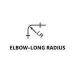 |
| 2.07 | Side Outlet Elbow– Outlet Down. | 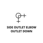 |
| 2.08 | Side Outlet Elbow– Outlet Up | 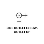 |
| 2.09 | Base Elbow | 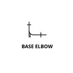 |
| 2.10 | Double Branch Elbow | 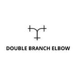 |
| 2.11 | Single Sweep Tee | 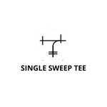 |
| 2.12 | Double Sweep Tee | 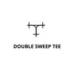 |
| 2.13 | Reducing Elbow | 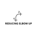 |
| 2.14 | Reducing Elbow Down | |
| 2.15 | Tee | 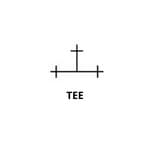 |
| 2.16 | Tee–Outlet Up | 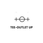 |
| 2.17 | Side Outlet Tee– Outlet Up | 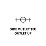 |
| 2.18 | Side Outlet Tee– Outlet Down | 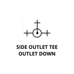 |
| 2.19 | Cross |  |
| 2.20 | Concentric Reducer |  |
| 2.21 | Eccentric Reducer |  |
| 2.22 | Lateral |  |
| 2.23 | Expansion Joint |  |
| 3.0 | Plumbing Valve Blueprint | Symbols |
| 3.01 | Gate Valve |  |
| 3.02 | Globe Valve |  |
| 3.03 | Angle Globe Valve |  |
| 3.04 | Angle Gate Valve |  |
| 3.05 | Check Valve |  |
| 3.06 | Angle Check Valve |  |
| 3.07 | Stop Cock |  |
| 3.08 | Safety Valve | 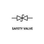 |
| 3.09 | Quick-Opening Valve | 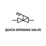 |
| 3.10 | Float Valve | 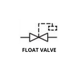 |
| 3.11 | Motor-Operated Gate Valve | 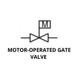 |
| 4.0 | Plumbing Fixture Blueprint | Symbols |
| 4.01 | Corner Bathtub | 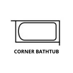 |
| 4.02 | Recessed Bathtub | 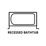 |
| 4.03 | Sitz Bath | 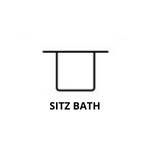 |
| 4.04 | Bidet | 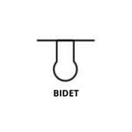 |
| 4.05 | Shower Stall | 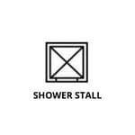 |
| 4.06 | Shower Head | 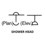 |
| 4.07 | Overhead Gang Shower | 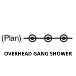 |
| 4.08 | Pedestal Lavatory | 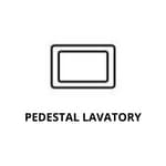 |
| 4.09 | Wall Lavatory | 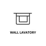 |
| 4.10 | Corner Lavatory |  |
| 4.11 | Handicapped Lavatory | 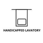 |
| 4.12 | Dental Lavatory | 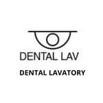 |
| 4.13 | Standard Kitchen Sink | 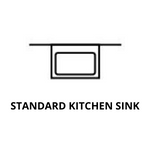 |
| 4.14 | Kitchen Sink, R & L Drain Board | 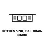 |
| 4.15 | Kitchen Sink, L H Drain Board | 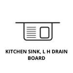 |
| 4.16 | Combination Sink & Dishwasher | 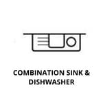 |
| 4.17 | Combination Sink & Laundry Tray | 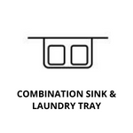 |
| 4.18 | Service Sink | 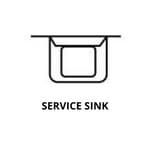 |
| 4.19 | Wash Sink (Wall-Type) | 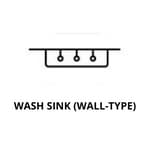 |
| 4.20 | Wash Sink | 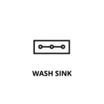 |
| 4.21 | Laundry Tray (Single) | 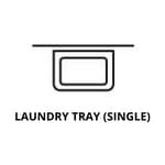 |
| 4.22 | Laundry Tray (Double) | 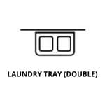 |
| 4.23 | Water Closet (Tank-Type) | 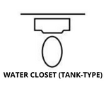 |
| 4.24 | Water Closet (Integral Tank) | 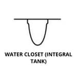 |
| 4.25 | Water Closet(FlushValve, Floor Outlet) | 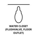 |
| 4.26 | Water Closet(FlushValve, Wall-Hung) | 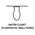 |
| 4.27 | Urinal (Wall-Hung) | 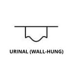 |
| 4.28 | Urinal (Stall) | 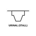 |
| 4.29 | Urinal (Trough-Type) | 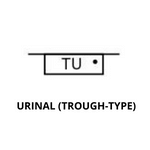 |
| 4.30 | Drinking Fountain (Recessed) |  |
| 4.31 | Drinking Fountain (Semi-Recessed) |  |
| 4.32 | Drinking Fountain (Projecting-Type) |  |
| 4.33 | Hot Water Tank |  |
| 4.34 | Water Heater |  |
| 4.35 | Meter |  |
| 4.36 | Hose Rack |  |
| 4.37 | Hose Bibb |  |
| 4.38 | Gas Outlet |  |
| 4.39 | Vacuum Outlet |  |
| 4.40 | Drain |  |
| 4.41 | Grease Separator |  |
| 4.42 | Oil Separator |  |
| 4.43 | Cleanout |  |
| 4.44 | Garage Drain |  |
| 4.45 | Floor Drain with Backwater Valve |  |
| 4.46 | Roof Sump | 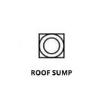 |
Architectural Floor Plan Symbols
Architectural floor plan symbols are various types and they are generally large in size.
Architectural symbols are generally categorized into four categories, those are- service symbols, lighting symbols, electrical symbols and plan-elevation-section symbols.
1. Service Blueprint Symbols:
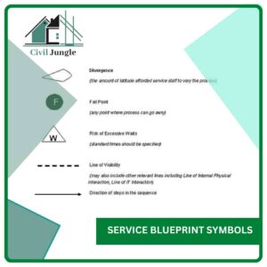
Service symbols are the mechanism symbols which are soil pipes, ventilation, etc.
| Sr.No. | Service Blueprint | Symbols |
| 1 | Rainwater Outlet |  |
| 2 | Soil Vent Pipe |  |
| 3 | Boiler Flue | 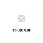 |
| 4 | Rainwater Hopper Outlet |  |
| 5 | Mechanical Fan Vent |  |
| 6 | Passive Vent |  |
| 7 | Direction of Drainage |  |
| 8 | Surface Water Drainage |  |
| 9 | Insulated Rain Water Pipe |  |
| 10 | Insulated Soil Vent Pipe |  |
| 11 | Soil Vent Pipe At Through Roof |  |
| 12 | Air Admittance Valve |  |
| 13 | Incoming Hot Water |  |
| 14 | Incoming Cool Water |  |
| 15 | Foul Water Run Above Ground |  |
2. Lighting Blueprint Symbols:
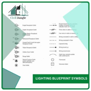
Here, all types of light symbols are discussed, there are various types.
| Sr.No. | Lighting Blueprint |
Symbols |
| 1 | Recessed Spot Light |  |
| 2 | Adjustable Recessed Spot- IP Rated |  |
| 3 | Recessed Spot Light- IP Rated |  |
| 4 | Recessed Floor Light |  |
| 5 | Underwater Light |  |
| 6 | Outdoor Plan Light |  |
| 7 | Pillar Light |  |
| 8 | Wall Light |  |
| 9 | Sensor Operated Wall Light |  |
| 10 | Surface Mounted Spot Light IP Rated |  |
| 11 | Recessed Stair Light |  |
| 12 | External Wall Mounted Light | 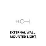 |
| 13 | LED Strip Light | 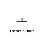 |
| 14 | Fluorescent Strip Light | 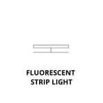 |
| 15 | Stick on Strip Light | 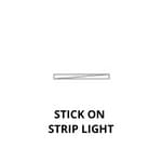 |
| 16 | Single Gang One Way Light Switch | 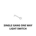 |
| 17 | Double Gang One Way Light Switch | 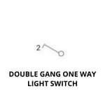 |
| 18 | Triple Gang One Way Light Switch | 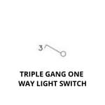 |
| 19 | Single Gang Two Way Light Switch | 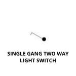 |
| 20 | Double Gang Two Way Light Switch | 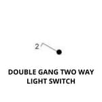 |
| 21 | Triple Gang Two Way Light Switch | 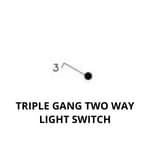 |
| 22 | Dimmer Light Switch | 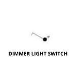 |
| 23 | 2 Way Dimmer Switch | 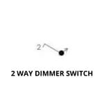 |
| 24 | 3 Way Dimmer Switch | 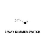 |
| 25 | PIR Sensor | 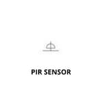 |
| 26 | Rocker Switch | 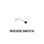 |
| 27 | Doorbell | 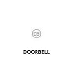 |
3. Electrical Blueprint Symbols
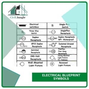
Electrical blueprint symbols are very important symbols in engineering drawing. Electrical symbols are included to omit the excess delay of an electric circuit.
Electrical blueprint symbols are used in engineering drawing to understand easily for workers and drafters.
Electrical blueprint symbols are in below-
| Sr.No. | Electrical Blueprint | Symbols |
| 1 | Single Power Socket | 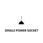 |
| 2 | Double Power Socket | 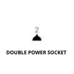 |
| 3 | Cooker Point | 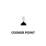 |
| 4 | Unswitched Fused Spur |  |
| 5 | External Power Socket |  |
| 6 | Telephone Point |  |
| 7 | Cat 6 Data Point |  |
| 8 | Extract Vent |  |
| 9 | Fire Alarm Panel |  |
| 10 | Shaver Socket |  |
| 11 | Speaker Point |  |
| 12 | TV Aerial Point |  |
| 13 | Floor Box |  |
| 14 | Floor Socket |  |
| 15 | Passive Extract |  |
| 16 | Mechanical Extract |  |
| 17 | Distribution Board |  |
| 18 | Smoke Detector |  |
| 19 | Heat Detector |  |
| 20 | Carbon Monoxide Detector |  |
| 21 | Extract Fan |  |
| 22 | Underfloor Heating Control |  |
FAQ: Blueprint Symbols
What Are Blueprint Symbols?
Blueprint symbols are standardized graphical representations used in engineering and architectural drawings to indicate objects, functions, or systems. These symbols help convey detailed information about the design and layout of a project.
What Types of Blueprints Use Symbols?
Symbols are used in various types of blueprints, including architectural drawings, structural plans, electrical schematics, HVAC (heating, ventilation, and air conditioning) plans, and plumbing layouts.
What Do Floor Plan Symbols Represent?
Floor plan symbols represent elements within a building layout as viewed from above. Common symbols include doors, windows, stairs, walls, and appliances. These symbols help in visualizing the arrangement of spaces and features.
How Are Hvac Symbols Used in Blueprints?
HVAC symbols denote components of heating, ventilation, and air conditioning systems. They include symbols for elements like heaters, air filters, air conditioners, vents, and ductwork, helping to plan the system’s layout and functionality.
What Are Plumbing and Piping Blueprint Symbols?
Plumbing and piping symbols represent various components in a plumbing system, including pipes, valves, fixtures, and fittings. These symbols are crucial for detailing the installation and routing of water, gas, and drainage systems.
What Are Architectural Floor Plan Symbols?
Architectural floor plan symbols represent elements of building design, including service symbols (e.g., rainwater outlets, soil vent pipes), lighting symbols (e.g., recessed spotlights, wall lights), and electrical symbols (e.g., power sockets, light switches).
How Do I Interpret Symbols on Blueprints?
To interpret symbols, refer to the blueprint’s legend or key, which provides explanations for each symbol used. Familiarize yourself with standard symbols and their meanings to accurately read and understand the drawing.
Why Are Standardized Symbols Important in Blueprints?
Standardized symbols ensure consistency and clarity in blueprints, making it easier for architects, engineers, and builders to communicate and understand design intentions. This helps in avoiding errors and misinterpretations during construction.
Where Can I Find More Information About Blueprint Symbols?
Additional information can be found in industry standards, design guides, and reference materials specific to architectural, electrical, HVAC, and plumbing fields. Professional organizations and educational resources often provide detailed guides and symbol directories.
Can Blueprint Symbols Vary by Region or Country?
Yes, while many symbols are standardized, there can be variations depending on regional or national practices. It’s important to use symbols that are appropriate for the specific standards and conventions of your location or project.