
What Is Auxiliary Plane?
Auxiliary Plane The plane which we draw to get the true shape of the inclined surface ( often parallel to Principal Plane ) is an auxiliary plane. Simply, the plane other than the Principal Plane ( i.e. Horizontal Plane, Vertical Plane or Perpendicular Plane) is called Auxiliary Plane.
Often one of the six principal views does not completely describe an object. This is justifiable when there are inclined or oblique planes or features on an object. For these special cases, a` special orthographic view called an auxiliary view is required to be created.
Types of Auxiliary Plane

Types of Auxiliary Plane there are two types. Which is as follows.
- Auxiliary Vertical Plane
- Auxiliary Inclined Plane
1. Auxiliary Vertical Plane
The plane which is perpendicular to a horizontal plane and inclined to the vertical plane is called an auxiliary vertical plane. This plane gives auxiliary front view.
2. Auxiliary Inclined Plane
The plane which is perpendicular to the vertical plane and inclined to the horizontal plane is called an auxiliary inclined plane. This plane gives auxiliary top view.
Definition of Auxiliary Views

An auxiliary view is an orthographic view projected in such a way that the lines of sight aren’t parallel to the principal projection planes (Frontal, Horizontal, or Profile).
Simply, the view which is obtained on the auxiliary plane is an auxiliary view. There is an infinite range of potential auxiliary views of any given object.
Auxiliary Views are often used to show the True Size of Inclined Surfaces as in generally inclined surfaces does not show their true size using standard orthographic drawing procedure. Normally the auxiliary plane is parallel to the inclined surface.
Method of Preparation of Auxiliary Views

Orthographic projections are prepared before making ready auxiliary views. The view within which inclined lines show actual length, perpendiculars are erected there with the inclined lines to get the particular length.
The breadth and alternative details are collected from the opposite view. Generally, the detail of the inclined surface is given within the auxiliary view. The opposite components within the principal plane are unheeded.
- Symmetrical Auxiliary View:
- Unsymmetrical Auxiliary View:
- Unilateral View:
- Bilateral View:
- Unilateral Auxiliary View:
- Bilateral Auxiliary View:
1. Symmetrical Auxiliary View
If the auxiliary view lies uniformly on each side of the reference line, then it’s reffered to as Symmetrical Auxiliary Views.
2. Unsymmetrical Auxiliary View
If the auxiliary view doesn’t lie uniformly on either side of the reference line, then it’s reffered to as Unsymmetrical Auxiliary Views.
There are two sorts of Unsymmetrical Auxiliary View:
2a. Unilateral View
If the auxiliary read lies utterly on one facet of the reference line, then it’s known as Unilateral view.
2b. Bilateral View
If the auxiliary read lies on one facet of the reference line asymmetrically, then it’s known as Bilateral view.
3. Unilateral Auxiliary View
If it lies on one facet solely of the reference line, then it’s known as Unilateral Auxiliary Views.
4. Bilateral Auxiliary View
If the auxiliary read doesn’t uniformly lie on each side of the reference line, then it’s known as Bilateral Auxiliary Views.
Types of Auxiliary View

Types of Auxiliary View there are three types. Which is as follows.
- Primary Auxiliary View.
- Secondary Auxiliary View.
- Tertiary Auxiliary View.
- Primary Auxiliary Views.
- Frontal Auxiliary View.
- High Auxiliary View.
- Profile/ Facet Auxiliary View.
- Secondary Auxiliary Views.
- Primary Auxiliary Views.
1. Primary Auxiliary View
The single view usually projected from one among the 6 principal views. If this plane is perpendicular to any principal plane, then a shape on such a drawing is called Primary Auxiliary Views.
2. Secondary Auxiliary View
The single view usually projected from another primary auxiliary view. If the auxiliary plane isn’t perpendicular to any principal plane, then the form shaped on such plane is named Secondary Auxiliary Views.
3. Tertiary Auxiliary View
The single view usually projected from a secondary/ tertiary auxiliary view. Classification of Auxiliary View with respect to inclined lines is as follows:
- Primary Auxiliary Views.
- Frontal Auxiliary View.
- High Auxiliary View.
- Profile/ Facet Auxiliary View.
- Secondary Auxiliary Views.
3.a. Primary Auxiliary Views
- Auxiliary View that is ready in such a plane that is perpendicular to 1 principal plane and makes the inclined view with the opposite two principal planes is named Primary Auxiliary read.
- There are three sorts of Primary Auxiliary Views because of three principal planes as follows:
3.a.1. Frontal Auxiliary View
- The name of auxiliary views are given in line with the inclined lines within the principal plane.
- For example, if the inclined surface is seen within the frontal plane, then such an auxiliary view is known as Frontal Auxiliary View.
- Frontal Auxiliary view While drawing, it’s hooked up to the frontal plane.
3.a.2. High Auxiliary View
- If the inclined surface is seen within the high plane, then such an auxiliary view is known as High Auxiliary View.
- If the inclined surface is perpendicular to the highest plane, then such an auxiliary are known as high Auxiliary Views.
- While drawing, it’s hooked up to the highest plane.
3.a.3. Profile/ Facet Auxiliary View
- Similarly, if the inclined surface is seen within the profile plane, then such an auxiliary view is known as Profile/Facet Auxiliary View.
- If the inclined surface is perpendicular to the profile plane, then such an auxiliary are known as Profile Auxiliary Views.
- While drawing, it’s hooked up to the profile plane.
#3.b. Secondary Auxiliary Views:
- Auxiliary View that is ready in such a plane that isn’t perpendicular to any of the principal planes is named Secondary Auxiliary Views.
- Such a view is created once the inclined surface of the article is neither parallel nor perpendicular with any of the principal planes.
- Such an auxiliary is named Double Auxiliary read.
How to Draw Auxiliary View?
To prepare an auxiliary view, the length and alternative detail regarding auxiliary views are obtained by taking projections from the inclined surface whereas, breadth and alternative detail are obtained from alternative views (like top view), for the completion of the auxiliary views.
Drawing Auxiliary Views
Once reading lines on the thing in an auxiliary view adjacent to a principal view, similar rules apply to reading lines in adjacent principal views.
To utilize an auxiliary view to indicate a surface’s true size (TS), a view should be drawn wherever that surface seems as a line. It’s impossible to indicate an oblique surface’s TS during a primary auxiliary view. Complete auxiliary views aren’t ordinarily drawn in business.
It is more common to ascertain partial auxiliary views that show solely the TS options. Since most of the opposite surfaces are going to be foreshortened, a whole auxiliary view becomes strenuous to scan.
- Depth auxiliary view: Generally projected from the front.
- Height auxiliary view: Generally projected from the top.
- Width auxiliary view: Generally projected from the profile.
There are two ways of viewing an auxiliary view:
- Complete Auxiliary View
- Partial Auxiliary View
1. Complete Auxiliary View
- This type of view allows the viewer to see the entire side of that drawing as projected from the auxiliary plane.
- With this projection, the other surfaces will appear fore-shortened which can make the drawing strenuous to read.
2. Partial Auxiliary View
- This type of projection allows the viewer to see only the part of that drawing that needs to be illustrated in its true undistorted surface.
- A partial auxiliary view saves precious time and produces a drawing that is much more readable. The full auxiliary view is strenuous to draw, read, and visualize.
Drawing Steps for Auxiliary View:
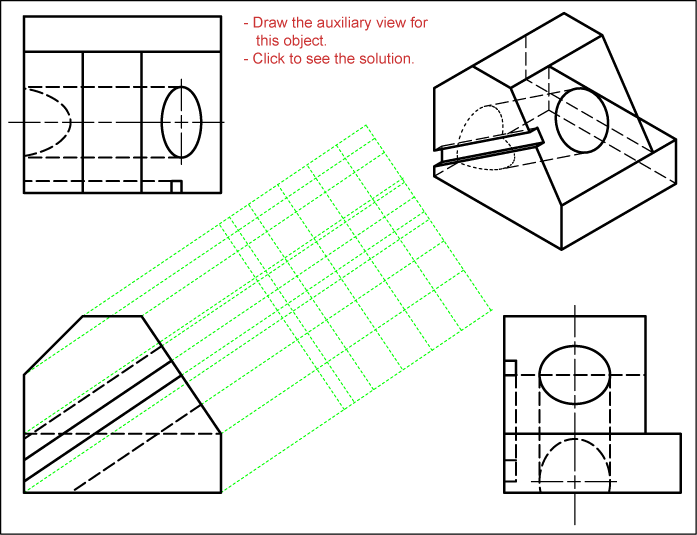
Step 1. Draw the given Orthographic View of the object.
Step 2. Draw the Auxiliary Plane(Take Centre Plane as Reference Plane).
Step 3. Apply the Centre Line Method and Copy the Distance from the Centre Line (Generally the Edge View is the Centre Line on the Top View).
Step 4. Draw the Projection Lines between the inclined surface and auxiliary plane.
Step 5. Complete the Final Auxiliary View by joining different points incorrect order.
Or,
Step 5. Examine the views that are supplied for an inclined surface.
Step 6 Locate the line which is considered as the edge view of the inclined plane.
Step 7. In the front view, draw light construction lines at right angles top the inclined surface. This is Line of Sight.
Step 8. Imagine the auxiliary plane as being attached by hinges to the front (vertical plane) from which it is developed.
Step 9. From all points labelled on the front view, draw projection lines at 90 Degree to the inclined surface (parallel to the line of sight).
Step 10. Construct a reference line collateral and equidistant to the edge view of the inclined surface.
Step 11. Transfer the Depth Dimension (In this case it is the Primary Reference to the Reference Line).
Step 12. Project the labelled points and join them in sequence to prepare the auxiliary view. The points used to identify the shape are for solving difficult problems on instructional purposes.
Why Are Auxiliary Views Used?
When making engineering drawings, it’s typically necessary to indicate options during a read wherever they seem true to size so they will be dimensioned.
The thing is generally positioned specified the most important surfaces and options are either parallel or perpendicular to the principal planes.
Views are commonly selected so most of the options are going to be visible within the 3 principal views. The front, top, and left or right facet views are most typically drawn.
Many objects are quite complicated, and therefore the three principal views might not best gift. During this case, one or additional auxiliary views generally are drawn.
FAQs on Auxiliary Planes in Orthographic Projection
What is an auxiliary plane?
An auxiliary plane is a plane used in orthographic projection to reveal the true shape of an inclined surface. It is different from the principal planes (Horizontal, Vertical, or Perpendicular).
Why is an auxiliary plane necessary?
An auxiliary plane is needed when one of the six principal views does not completely describe an object, especially when there are inclined or oblique planes or features.
What are the types of auxiliary planes?
There are two main types of auxiliary planes:
- Auxiliary Vertical Plane (AVP): Perpendicular to the horizontal plane and inclined to the vertical plane, giving an auxiliary front view.
- Auxiliary Inclined Plane (AIP): Perpendicular to the vertical plane and inclined to the horizontal plane, giving an auxiliary top view.
What is an auxiliary view?
An auxiliary view is an orthographic view projected such that the lines of sight are not parallel to the principal projection planes. It shows the true size of inclined surfaces.
What are the types of auxiliary views?
There are three types of auxiliary views:
- Primary Auxiliary View: Projected from one of the principal views.
- Secondary Auxiliary View: Projected from a primary auxiliary view.
- Tertiary Auxiliary View: Projected from a secondary or another tertiary auxiliary view.
How do you prepare an auxiliary view?
Steps to prepare an auxiliary view include:
-
- Draw the orthographic view of the object.
- Draw the auxiliary plane.
- Apply the center line method and copy distances from the center line.
- Draw projection lines between the inclined surface and the auxiliary plane.
- Complete the auxiliary view by joining points in the correct order.
What is the difference between a complete and partial auxiliary view?
A complete auxiliary view shows the entire side of the drawing projected from the auxiliary plane, while a partial auxiliary view shows only the necessary part of the drawing, making it easier to read and saving time.
What are symmetrical and unsymmetrical auxiliary views?
- Symmetrical Auxiliary View: Lies uniformly on each side of the reference line.
- Unsymmetrical Auxiliary View: Does not lie uniformly on either side of the reference line and can be unilateral (on one side) or bilateral (asymmetrical on one side).
What are the benefits of using auxiliary views in engineering drawings?
Auxiliary views help in accurately showing features in their true size, which is essential for dimensioning. They provide a more comprehensive understanding of complex objects that principal views might not fully represent.
When should you use an auxiliary view?
Use an auxiliary view when the object’s features are not adequately described by the principal views, particularly for inclined or oblique surfaces that need to be shown in true size.
How does an auxiliary view help in visualizing an object?
Auxiliary views help by providing a clear and true representation of inclined surfaces, making it easier to understand and visualize the object’s geometry and dimensions.
Can auxiliary views be used for all objects?
While auxiliary views are particularly useful for complex objects with inclined surfaces, they can be applied to any object where the principal views do not provide sufficient detail.